Connections and Wiring
25
NI-2100, NI-3100, NI-4100 Hardware Reference Guide
DB9 Device Port: Connections and Wiring
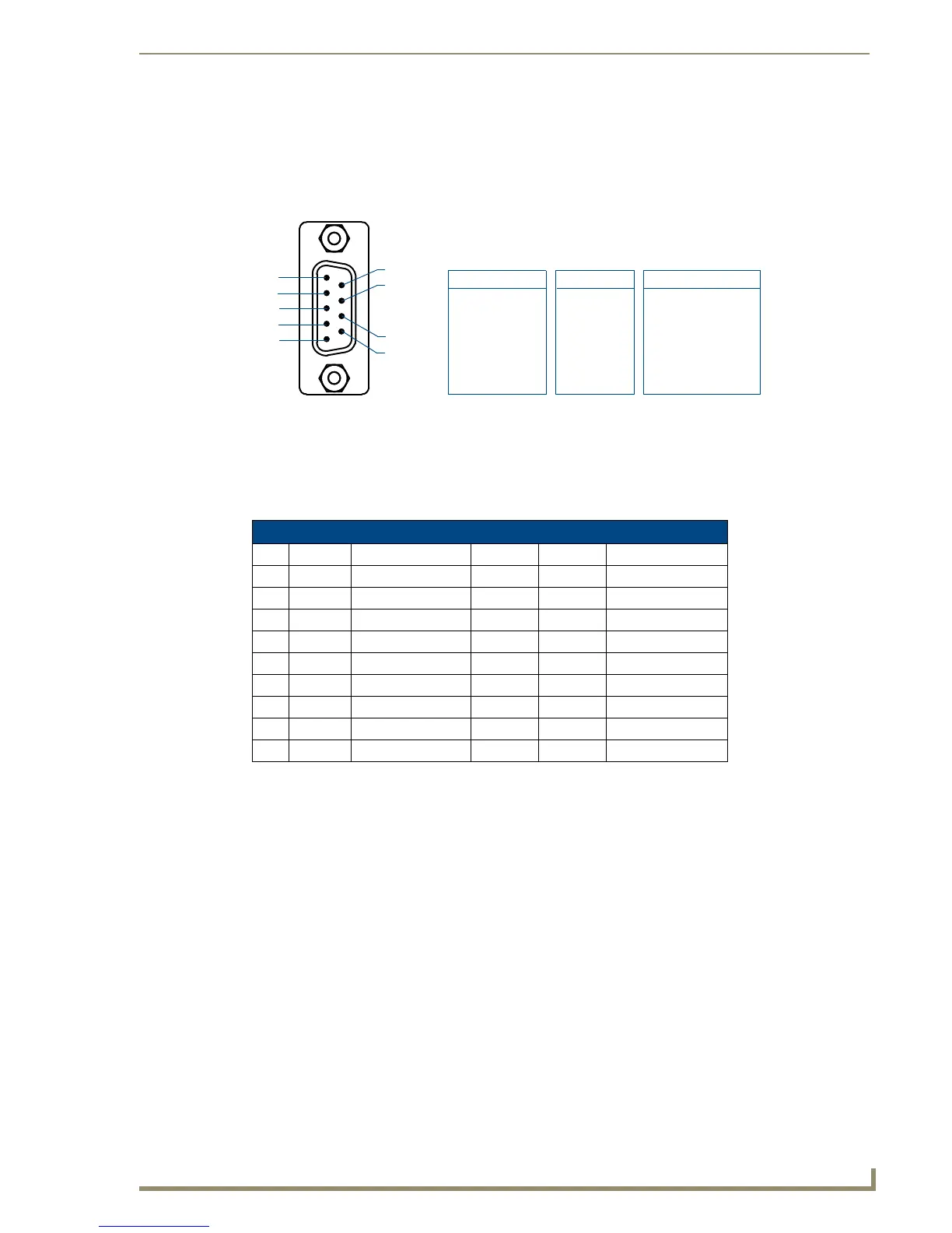
FIG. 12 shows the connector pinouts for the rear RS-232/RS-422/RS-485 (DB9) Device Ports.
These ports support most standard RS-232 communication protocols for data transmission. This figure gives a
visual representation of the wiring specifications for the RS-232/422/485 Device connectors. Refer to the rear
of the unit for more detailed connector pinout information.
The table below provides information about the connector pins, signal types, and signal functions. This table’s
wiring specifications are applicable to the rear RS-232/422/485 Device Port connectors on the:
NI-2100 (Ports 1-3)
NI-4100/NI-3100 (Ports 1-7)
FIG. 12 RS-232/422/485 DB9 (male) connector pinouts for the rear Device Ports
RS-232/422/485 Device Port Wiring Specifications
Pin Signal Function RS-232 RS-422 RS-485
1 RX- Receive data X X (strap to pin 9)
2 RXD Receive data X
3 TXD Transmit data X
4 TX+ Transmit data X X (strap to pin 6)
5 GND Signal ground X X
6 RX+ Receive data X X (strap to pin 4)
7 RTS Request to send X
8 CTS Clear to send X
9 TX- Transmit data X X (strap to pin 1)
5
4
3
2
1
9
8
7
6
Male
DB9 Serial Port pinouts (male connector)
Pin 2: RX signal
Pin 3: TX signal
Pin 5: GND
Pin 7: RTS
Pin 8: CTS
RS-232
Pin 1: RX -
Pin 4: TX +
Pin 5: GND
Pin 6: RX +
Pin 9: TX -
RS-422
Pin 1: A (strap to 9)
Pin 4: B (strap to 6)
Pin 5: GND
Pin 6: B (strap to 4)
Pin 9: A (strap to 1)
RS-485
 Loading...