Connections and Wiring
26
NI-2100, NI-3100, NI-4100 Hardware Reference Guide
ICSNet Port: Connections and Wiring
The NI Controller must be equipped with the available ICSNet connectors for this functionality to be active.
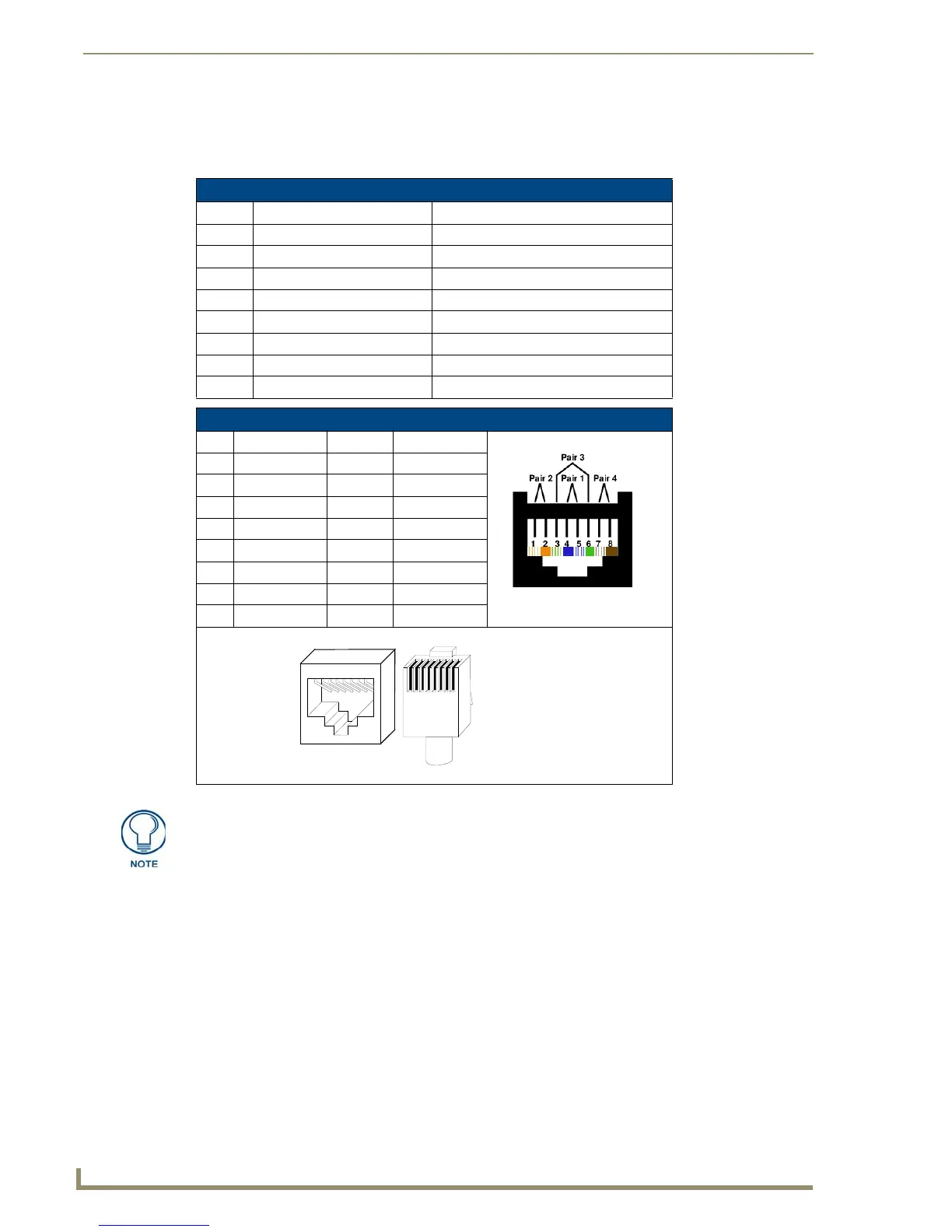
The following tables show the signal and pinouts/pairing information:
ICSNet RJ-45 Signals
Pin Signal-Master Signal-Device
1 TX + RX +
2TX - RX -
3N/A N/A
4GND GND
5N/A N/A
6N/A N/A
7 RX + TX +
8 RX - TX -
RJ-45 Pinout Information (EIA/TIA 568 B)
Pin Wire Color Polarity Function
1 Orange/White + Transmit
2 Orange - Transmit
3 Green/White - Mic
4 Blue - Ground
5 White/Blue + 12 VDC
6 Green + Mic
7 White/Brown + Receive
8 Brown - Receive
RJ-45 connector - pin configurations
(female) (male)
Unlike the ICSNet ports, the ICSHub connections require a specific polarity. The
IN/OUT configuration, on the hub ports, was implemented to use the same cables as
ICSNet, but these ports need TX and RX crossed. You must connect an OUT to an
IN, or an IN to an OUT port.
This is done simply to keep the polarity straight. The Hub bus is still a bus. All Hub
connections are bi-directional.
 Loading...