Connections and Wiring
28
NI-2100, NI-3100, NI-4100 Hardware Reference Guide
Input/Output (I/O) Port: Connections and Wiring
The I/O port responds to either switch closures, voltage level (high/low) changes, or it can be used for logic-
level outputs.
A contact closure between the GND and an I/O port is detected as a Push.
When used for voltage inputs, the I/O port detects a low signal (0 - 1.5 VDC) as a Push, and a high
signal (3.5 - 5 VDC) as a Release (this IO port uses 5V logic but can handle up to 12V without
harm).
When used for outputs, the I/O port acts as a switch to GND and is rated for 200mA @ 12 VDC.
The NI-2100 can use up to 4 I/O ports
The NI-3100 and NI-4100 can use up to 8 I/O ports
The PWR pin provides +12 VDC @ 200 mA and is designed as a power output for the PCS Power
Current Sensors, VSS2 Video Sync Sensors (or equivalent).
The GND connector is a common ground and is shared by all I/O ports. A common ground is
shared with I/O ports 1 - 8 (NI-3100/NI-4100) or with I/O ports 1 - 3 (NI-2100).
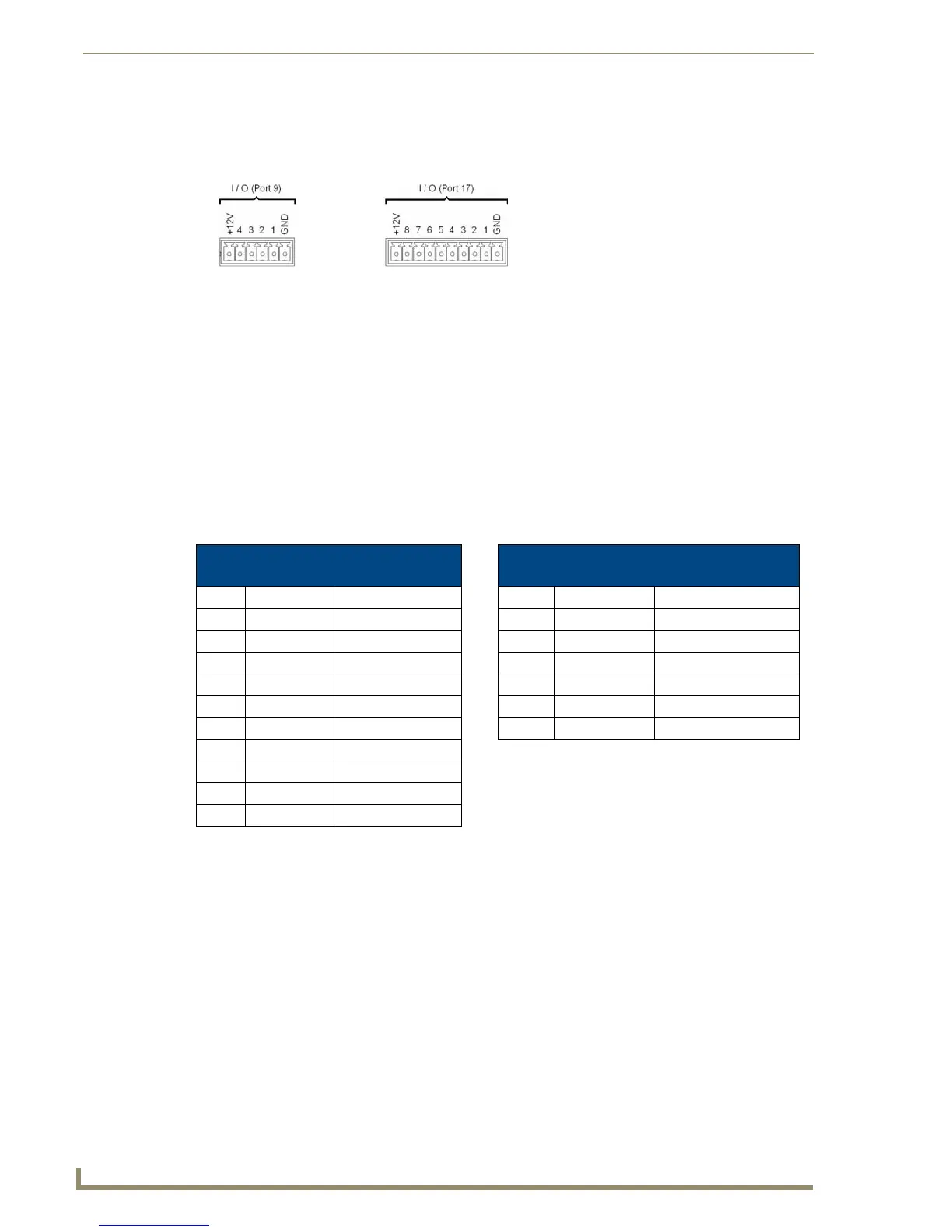
FIG. 14 INPUT/OUTPUT (I/O) connector (male)
I/O Port Wiring Specifications
NI-4100 and NI-3100
I/O Port Wiring Specifications NI-2100
Pin Signal Function Pin Signal Function
1 GND Signal GND 1 GND Signal GND
2 I/O 1 Input/Output 2 I/O 1 Input/Output
3 I/O 2 Input/Output 3 I/O 2 Input/Output
4 I/O 3 Input/Output 4 I/O 3 Input/Output
5 I/O 4 Input/Output 5 I/O 4 Input/Output
6 I/O 5 Input/Output 6 12 VDC PWR
7 I/O 6 Input/Output
8 I/O 7 Input/Output
9 I/O 8 Input/Output
10 12 VDC PWR
NI-4100/NI-3100 I/O connector
configuration (Port 17)
NI-2100 I/O connector
configuration (Port 9)
 Loading...