Introduction
4
NI-2100, NI-3100, NI-4100 Hardware Reference Guide
NI-2100 Specifications (Cont.)
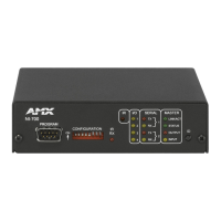
Front Panel LEDs:
LINK/ACT (green): Blinks when the Ethernet cables are connected and terminated correctly. Also blinks
when receiving Ethernet data packets.
Status (green): Blinks to indicate that the system is programmed and communicating properly.
Output (red): Blinks when the Controller transmits data, sets channels On and Off, sends data strings,
etc.
Input (yellow): Blinks when the Controller receives data from button pushes, strings, commands,
channel levels, etc.
RS-232/422/485
(red / yellow):
3 sets of LEDs light to indicate that DB9 Ports 1 - 3 are transmitting or receiving RS-232,
422, or 485 data (red = TX, yellow = RX).
Relay (red): 4 LEDs light to indicate the relay channels 1 - 4 are active (closed). These LEDs reflect
the state of the relay on Port 4.
IR/Serial (red): 4 LEDs light to indicate the IR/Serial channels 1 - 4 are transmitting control data on
Ports 5 - 8. LED indictor for each IR port remains lit for the length of time that IR/Serial
data is being generated.
I/O (yellow): Lights when the I/O channels 1 - 4 are active. The LED for each I/O port reflects the
state of that particular port.
RS-232/422/485
(Ports 1 - 3):
3 RS-232/422/485 control ports using DB9 (male) connectors with XON/XOFF (transmit
on/transmit off), CTS/RTS (clear to send/ready to send), and 300-115,200 baud.
ICSNet: 2 RJ-45 connectors for ICSNet interface (provided by optional ICSNet daughter card).
ICSHub Out: RJ-45 connector provides data to a Hub connected to the Controller (provided by
optional ICSNet daughter card).
Relay (Port 4): • 4-channel single-pole single-throw relay ports
• Each relay is independently controlled.
• Supports up to 4 independent external relay devices
• Channel range = 1-4
• Each relay can switch up to 24 VDC or 28 VAC @ 1 A
• 8-pin 3.5 mm mini-Phoenix (female) connector provides relay termination
Digital I/O (Port 9): 4-channel binary I/O port for contact closure with each input being capable of voltage
sensing. Input format is software selectable with interactive power sensing for IR ports.
IR/Serial
(Ports 5 - 8):
4 IR/Serial control ports support high-frequency carriers of up to 1.142 MHz with each
output being capable of two electrical formats: IR or Serial.
• 4 IR/Serial data signals can be generated simultaneously.
• IR ports support data mode (at limited baud rates and wiring distances).
Rear Panel Components:
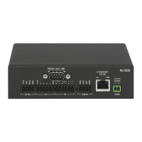
Program Port: RS-232 DB9 connector (male) can be connected to a DB9 port on a PC. This connector
can be used with serial and NetLinx programming commands, as well as other DB9
capable devices, to both upload/download information from the NetLinx Studio program.
Configuration DIP
Switch:
Sets the communication parameters for the Program port (see Baud Rate Settings).
ID Pushbutton: Sets the NetLinx ID (Device only) assignment for the device.
Ethernet Port: RJ-45 connector provides TCP/IP communication. This is an Auto MDI/MDI-X enabled
port, which allows you to use either straight-through or crossover Ethernet cables.
The Ethernet Port LEDs show communication activity, connection status, speeds, and
mode information:
• SPD (speed) - Yellow LED lights On when the connection speed is 100 Mbps and
turns Off when the speed is 10 Mbps.
• L/A (link/activity) - Green LED lights On when the Ethernet cables are connected and
terminated correctly, and blinks when receiving Ethernet data packets.
AxLink Port: 4-pin 3.5 mm mini-Phoenix (male) connector that provides data and power to external
control devices. Green AXlink LED indicates the state of the AXlink port.
 Loading...
