Preliminary Technical Data UG-1828
Rev. PrC | Page 115 of 338
Delay Parameter Descriptions Bounds Notes
enableFallToOffDelay Delay between the
hop edge and
powering down the
analog and Tx antenna
switch. Not used in
frequency hopping.
NA Hop edge indicates the end of frame on air. The
analog and Tx antenna switch can be powered
down immediately.
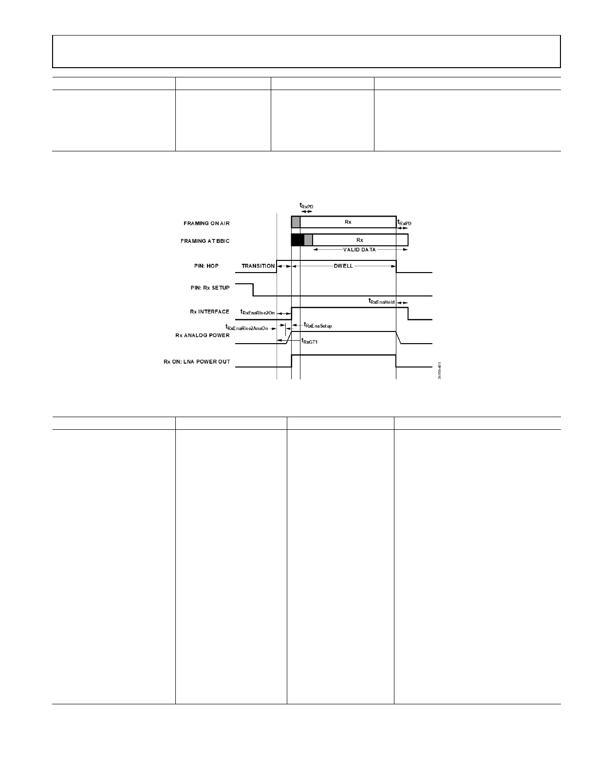
Rx Timing
Figure 115. Rx Timing
Table 42. Rx Timing Parameters
Delay Parameter Descriptions Bounds Notes
enableSetupDelay
(trxEnaSetup)
Time taken for ADRV9001
to power up the AFE. This
time may or may not
include PLL retuning time.
N/A No PLL retuning @ hop edge: 7 µs
PLL retuning @ frame boundary:
LO_retune_time
propagationDelay Delay from antenna to Rx
interface.
N/A This parameter will be dynamic profile
dependent and board layout dependent.
Not necessary to configure ADRV9001, but
may be necessary to derive other timing
parameters
enableRiseToOnDelay Delay between hop edge
and the LNA power up. If
ADRV9001 is not
controlling LNA powerup,
this variable is not needed.
Min:
enableRiseToOnDelay +
enableSetupDelay
Max: -
analogGuardTime Minimum time between
the hop edge and analog
power up to prevent Rx
and Tx FE being powered
up at the same time.
N/A Min/max: 0.15 µs
enableRiseToAnalogOnDelay
(tRxEnaRiseToAnaOn)
Delays the power up of the
AFE relative to the hop
edge.
Min: analogGuardTime
Max: -
The minimum time of this delay is the
analogGuardTime.
enableGuardDelay
(tRxGT1)
Delay between hop edge
and first valid data received
over the air.
Min:
enableRiseToOnDelay +
enableSetupDelay
Max: 0
Not used currently but can be used to
delay starting of the tracking algorithms
until the first valid data is received over the
air.
 Loading...