UG-1828 Preliminary Technical Data
Rev. PrC | Page 156 of 338
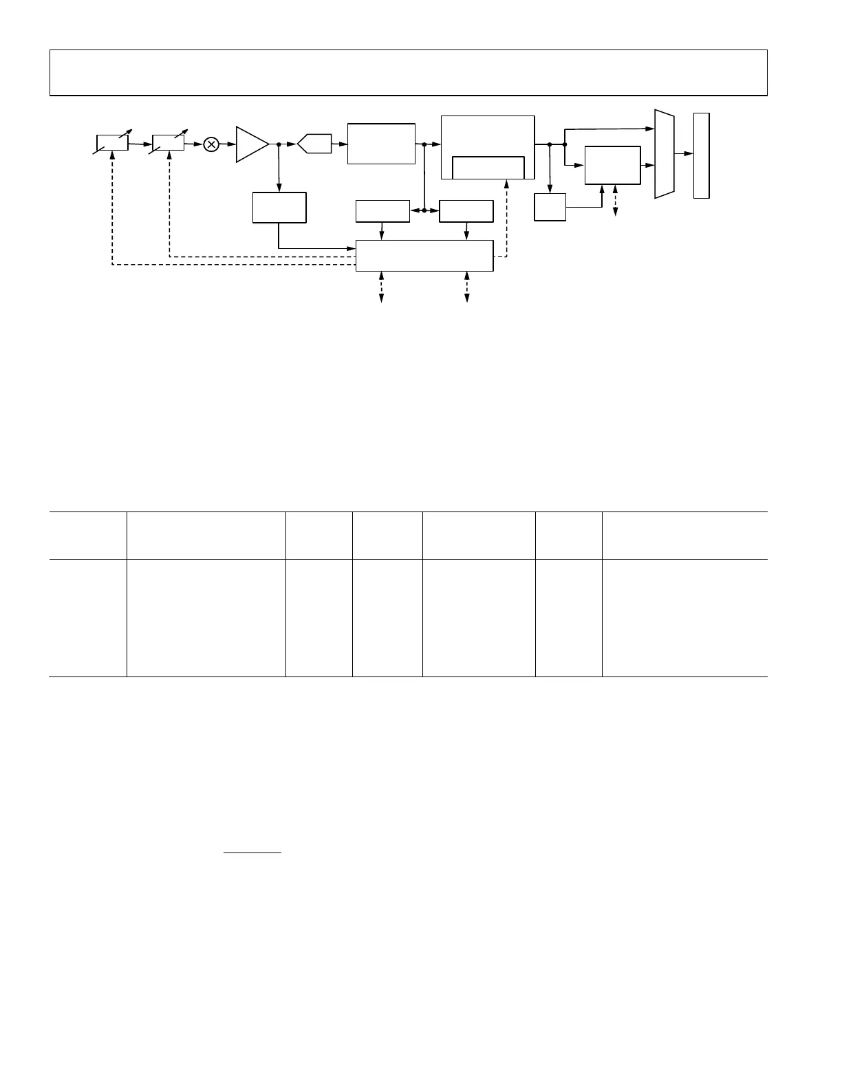
Figure 148. Rx Data Path and Gain Control Blocks
In this gain table, each row provides a unique combination of 6 fields including Front-end Attenuator, TIA Control, ADC Control,
External Gain Control, Phase Offset and Digital Gain/Attenuator. Among them, the TIA Control which sets the TIA gain, the ADC
Control which sets the ADC gain and the Phase Offset which compensates for the phase discontinuity during gain change are reserved for
future use.
Based on the row of this table selected, either by the user in MGC mode, or automatically by the device in AGC mode, the gain control
block updates the variable gain elements depicted by the dash lines. In the MGC mode, the user can control the gain control block using
the API commands and DGPIOs.
Table 56 shows the first three and last three rows in a sample gain table.
Table 56. Sample Rows from the Default Rx Gain Table
Gain Table
Index
Front-End Attenuator
Control Word [7:0]
TIA
Control
ADC
Control
External Gain
Control [1:0]
Phase
Offset
Digital Gain/Attenuator
Control Word
[10:0]
188 247 0 0 0 0 -17
189 250 0 0 0 0 −4
… … … … … … …
253 28 0 0 0 0 −2
255 0 0 0 0 0 0
The gain table index is the reference for each unique combination of gain settings in the programmable gain table. The current possible
range of the gain table is 187 to 255. The gain index region is user configurable. An API function
adi_adrv9001_Rx_MinMaxGainIndex_Set() could be called by the user right after loading the gain table to load multiple gain table
regions and switch between multiple gain table regions during runtime.
The 2 fields which are used in the default gain table are the Front-end Attenuator and the Digital Gain/Attenuator. The Front-end
Attenuator is an 8-bit control word. The amount of attenuation applied depends on the value set in this column of the selected gain table
index. The following equation provides an approximate relationship between the internal attenuator and the front-end attenuation value
programmed in the gain table, N:
Attenuation (dB) = 20log
10
It can be seen that index 255 denotes a 0dB Front-end attenuation and the step size between adjacent gain index is approximately 0.5dB.
Note when the index is below 195, the actual step size become less accurate.
The Digital Gain/Attenuator column is used to apply gain or attenuation digitally. The 11-bit signed word defines the digital gain applied,
which equals to the control word times 0.05 in dB. As shown in Table 56, for gain index 253, the digital gain can be calculated as -2*0.05 =
-0.1dB.
2 Types of receiver gain tables are provided. One is for gain correction in which the digital gain is for correcting the small step size
inaccuracy in the Front-end Attenuator. The other is for gain compensation which compensates the entire front-end attenuation. The
WB/NB DECIMATION
(DECIMATION
STAGE 2)
HB FILTERING
(DECIMATION
STAGE 1)
INTERFACE
GAIN
(SLICER)
LVDS/CMOS
API
API DGPIO(S)
RSSI
HB PEAK
DETECTOR
POWER
DETECTOR
ANALOG
PEAK
DETECTOR
GAIN CONTROL BLOCK
(AGC, MGC)
FRONT END
ATTENUATOR
MUX
DIGITAL
GAIN CONTROL
ADC
TIA
GAIN
EXTERNAL
GAIN
GAIN
24159-106
 Loading...