Preliminary Technical Data UG-1828
Rev. PrC | Page 231 of 338
Figure 211. ADRV9001 RX B Port Series Equivalent Differential Impedance
ADS Setup Using DAC and SEDZ File
ADI supplies the port impedance as an *.s1p Series Equivalent Differential Z(impedance) file. This format allows simple interface to ADS
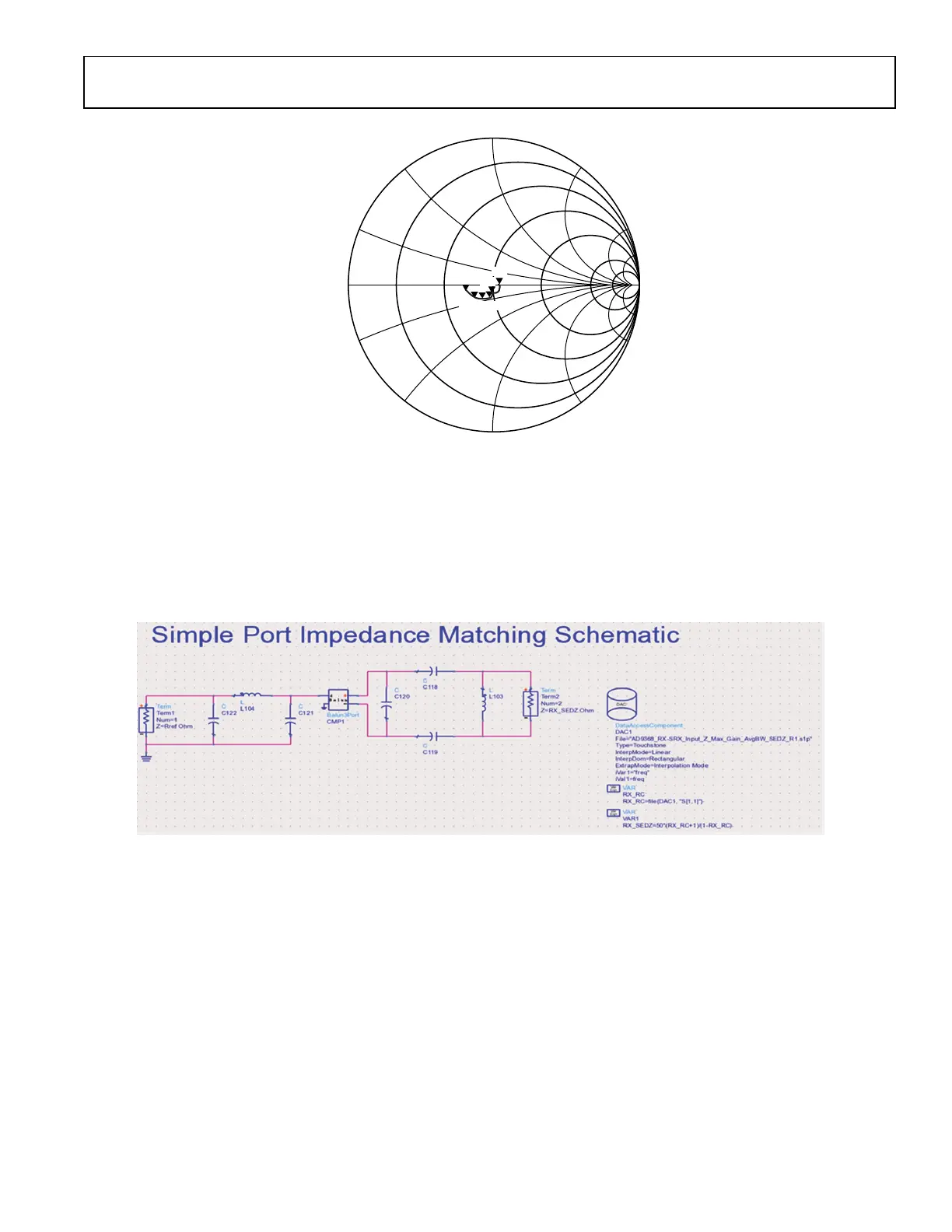
by using the Data Access Component (DAC). In the below diagram Term1 is the single ended input or output and Term2 represents the
differential input or output RF port on ADRV9001. The Pi on the single ended side and the differential Pi configuration on the
differential side allows maximum flexibility in designing matching circuits, and is suggested for all design layouts as it can step the
impedance up or down as needed with appropriate component population.
Figure 212. Simulation Setup in ADS with SEDZ S1P Files and DAC Component
Operation is as follows:
1. The DAC block reads the rf port*.s1p file. This is the device RF port reflection coefficient.
2. The two equations convert the RF port reflection coefficient to a complex impedance. The end result is the RX_SEDZ variable.
3. The RF port calculated complex impedance (RX_SEDZ) is used to define the Term2 impedance.
a. Term2 is used in differential mode and Term1 is used in single-ended mode.
Setting up the simulation this way allows one to measure the S11, S22, and S21 of the 3-port system without complex math operations
within the display page.
Note for highest accuracy, EM modelling result of the PCB artwork and S-parameters of the matching components and balun should be
used in the simulations.
The first differential shunt reactive component such as L103 in Figure 212, is inserted to tune out parallel parasitic reactance of input
impedance of the device. If ac-coupling cap is necessary, C118 and C119 can be used used for this purpose.
For a wideband match application, because of well controlled input/output impedance characteristics of ADRV9001 for entire range of its
RX/TX operational frequency band, minimal matching network can be implemented to control undesirable impedance deviation
typically associated with the high side of frequency range a balun operates. Additionally, by selecting a balun with the same differential
0
5.0
–5.0
2.0
1.0
–1.0
–2.0
0.5
–0.5
0.2
–0.2
m1
FREQUENCY = 30.00MHz
S(2,2) = 0.033/26.630
IMPEDANCE = 106.055 + j3.153
m2
FREQUENCY = 1.000GHz
S(2,2) = 0.051/–113.978
IMPEDANCE = 95.566 – j8.865
m3
FREQUENCY = 6.000GHz
S(2,2) = 0.083/–104.261
IMPEDANCE = 94.788 – j15.342
m6
FREQUENCY = 6.000GHz
S(2,2) = 0.193/–170.932
IMPEDANCE = 67.838 – j4.293
m5
FREQUENCY = 4.500GHz
S(2,2) = 0.152/–150.217
IMPEDANCE = 75.844 – j 11.760
m4
FREQUENCY = 3.000GHz
S(2,2) = 0.108/–129.045
IMPEDANCE = 86.136 – j14.596
FREQUENCY (30.00MHz TO 6.000GHz)
S(2,2)
M6
M5
M4 M3
M2
M1
24159-161
 Loading...