Preliminary Technical Data UG-1828
Rev. PrC | Page 267 of 338
iterative electromagnetic simulation to minimize magnetic field coupling between differential paths. These techniques are illustrated in
Figure 256.
Figure 256. RF I/O Isolation Structures
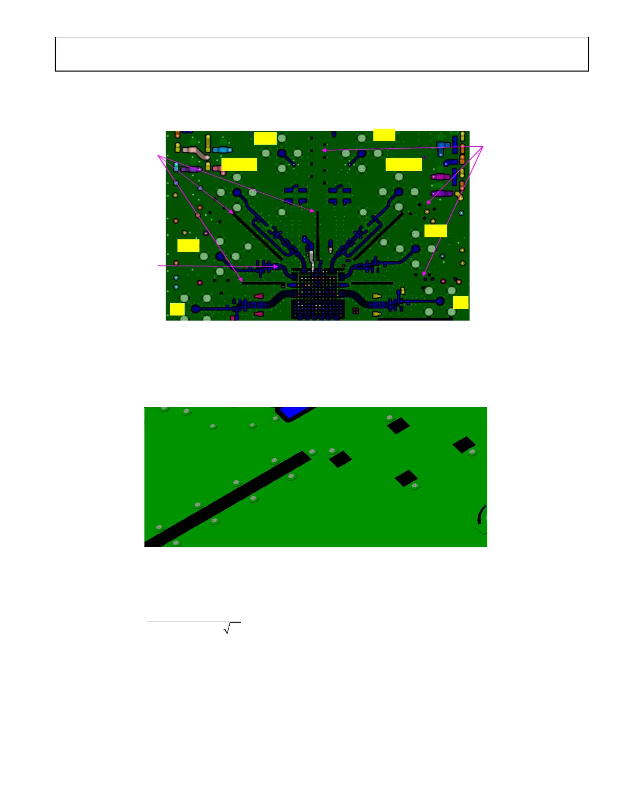
When utilizing the proposed isolating structures, it is important to place ground vias around the slots and apertures. Figure 257 illustrates
the methodology used on the ADRV9001 evaluation card. When slots are used, ground vias should be placed at each end of the slots and
along each side. When square apertures are used, at least one single ground via should be placed adjacent to each square. These vias
should be through-hole vias connecting the top to the bottom layer and all layers in between. The function of these vias is to steer return
current to the ground planes near the apertures.
Figure 257. Current Steering Vias Placed Near Isolation Slots and Square Apertures
For accurate slot spacing and square apertures layout, simulation software should be used when designing a PCB for an ADRV9001 based
transceiver. As a general rule, spacing between square apertures should be no more than 1/10 of the shortest wavelength supported. The
wavelength can be calculated using Equation 1
300
[]
[]
r
Wave length m
Frequency MHz
ε
=
×
(1)
where:
ε
r
is the dielectric constant of the isolator material. For ISOLA I-speed material, ε
r
= 3.56 and for FR4-408 HR material, ε
r
= 3.77.
Example: given a maximum RF signal frequency of 6 GHz, for ISOLA I-speed material, using microstrip structures, and ε
r
= 3.56, the
minimum wavelength is approximately 26.4 mm To fulfil the 1/10 of a wavelength rule, square aperture spacing should be at a distance of
2.64 mm or closer.
Additional shielding is provided by using connecting VSSA balls under the device to form a shield around RF IO ball pairs. This ground
provides a termination for stray electric fields. Figure 250 shows how this is done for Tx1. The same is done for each set of sensitive RF
I/O ports. Ground vias are used along single ended RF IO traces. Optimal via spacing is 1/10 of a wavelength, but that spacing can vary
somewhat due to practical layout considerations.
ISOLATION STRUCTURES
SQUARE APERTURES
ISOLATION STRUCTURES
SLOTS
DIFFERENTIAL PATH
ROUTING
Tx2
Tx1
Rx2A
Rx1A
Rx1B
Rx2B
Ext_LO2
24159-203
 Loading...