UG-1828 Preliminary Technical Data
Rev. PrC | Page 78 of 338
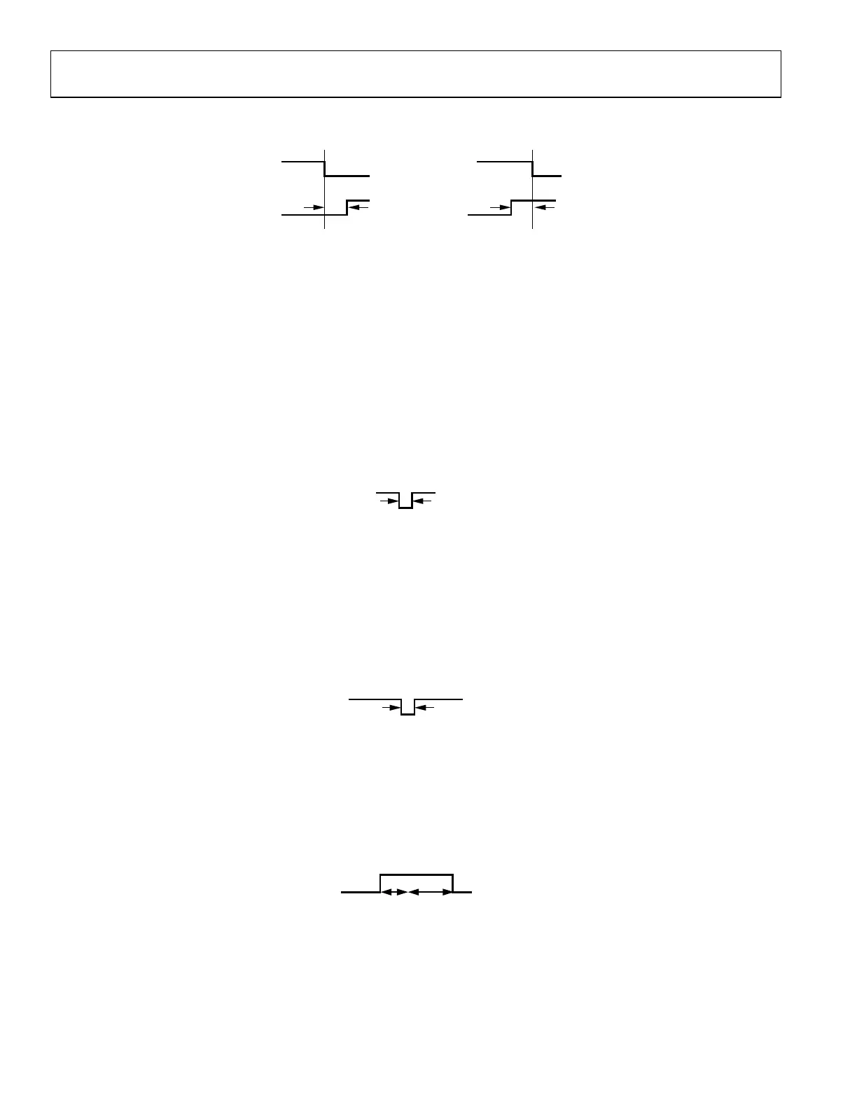
rising edge, the minimum guard time is t
RxEnaFall2Off
– t
TxEnaRise2On
if t
RxEnaFall2Off
is greater than t
TxEnaRise2On
. In the case of t
RxEnaFall2Off
is less than
t
TxEnaRise2On
, TX_ENABLE rising edge could happen t
TxEnaRise2On
− t
RxEnaFall2Off
before TX_ENABLE falling edge. Figure 67 describes both cases.
Figure 67. Minimum Guard Time Between RX_ENABLE Falling Edge and TX_ENABLE Rising Edge
Guard Time Between TX_ENABLE Falling Edge and TX_ENABLE Rising Edge
The guard time between TX_ENABLE falling edge and TX_ENABLE rising edge is for making sure that the interface is turned off at the
end of the previous frame before it turns on again for the next frame. In addition, it must also make sure that the analog front end has
been powered off in the previous frame prior to powering up again in the new frame. Because it takes t
TxEnaHold
to turn off the transmit
interface after the TX_ENABLE falling edge, the next TX_ENABLE rising edge must come after a delay of at least t
TxEnaHold
. This ensures
that the interface is turned off at the end of the previous frame before it turns on again for the next frame. Since it takes t
TxEnaFall2Off
to
power down the transmitter analog front end after the TX_ENABLE falling edge, the next TX_ENABLE rising edge must come after a
delay of at least equal to t
TxEnaFall2Off
− t
TxEnaRise2AnaOn
. This ensures that the analog front end has been powered off in the previous frame prior
to powering up again in the new frame. If the timing parameters are set appropriately, these two conditions are almost identical. If they
are not identical for some reason, the guard time should be set as the maximum of t
TxEnaHold
and t
TxEnaFall2Off
− t
TxEnaRise2AnaOn
. Figure 68
describes this scenario.
Figure 68. Minimum Guard Time Between TX_ENABLE Falling Edge and TX_ENABLE Rising Edge
Guard Time Between RX_ENABLE Falling Edge and RX_ENABLE Rising Edge
The guard time between the RX_ENABLE falling edge and RX_ENABLE rising edge is for making sure that the interface is turned off at
the end of the previous frame before it turns on again for the next frame. Because it takes t
RxEnaHold
to turn off the receive interface after the
RX_ENABLE falling edge, the next RX_ENABLE rising edge must come after a delay of at least t
RxEnaHold
. This ensures that the interface is
turned off at the end of the previous frame before it turns on again for the next frame. Because the analog powers down before the
interface, the analog front end is guaranteed to power down prior to being powered up at the start of the next frame if this condition is
met. Figure 69 describes this scenario.
Figure 69. Minimum Guard Time Between RX_ENABLE Falling Edge and RX_ENABLE Rising Edge
Hold Time Between TX_ENABLE Rising Edge and TX_ENABLE Falling Edge
After a TX_ENABLE rising edge, its falling edge must come after a delay of at least t
TxEnaRise2AnaOn
or t
TxEnaRise2On
(if controlling antenna
switch). In order to actually transmit, the channel must be on for a duration longer than its propagation delay. This can be achieved, either
by making sure TX_ENABLE is high for longer than the propagation delay, or by ensuring the t
TxEnaHold
and t
TxEnaFall2Off
are longer than t
TxPD
.
Figure 70 describes this scenario.
Figure 70. Minimum Hold Time between TX_ENABLE Rising Edge and TX_ENABLE Falling Edge
Hold Time Between RX_ENABLE Rising Edge and RX_ENABLE Falling Edge
After a RX_ENABLE rising edge, its falling edge must come after a delay of at least t
RxEnaRise2AnaOn
or t
RxEnaRise2On
(if controlling LNA power).
In order to actually receive data, the channel must be on for a duration longer than its propagation delay. This can be achieved, either by
making sure RX_ENABLE is high for longer than the propagation delay or by ensuring the t
RxEnaHold
is longer than t
RxPD
. Figure 71
describes this scenario.
Rx_ENABLE
Tx_ENABLE
t
RxEnaFall2Off
– t
TxEnaRise2On
Rx_ENABLE
Tx_ENABLE
t
TxEnaRise2On
– t
RxEnaFall2Off
t
RxEnaFall2Off
> t
TxEnaRise2On
t
RxEnaFall2Off
< t
TxEnaRise2On
24159-059
Tx_ENABLE
MAX (t
TxEnaHold
, t
TxEnaFall2Off
– t
TxEnaRise2On
)
24159-060
Rx_ENABLE
t
RxEnaHold
24159-061
 Loading...