Preliminary Technical Data UG-1828
Rev. PrC | Page 95 of 338
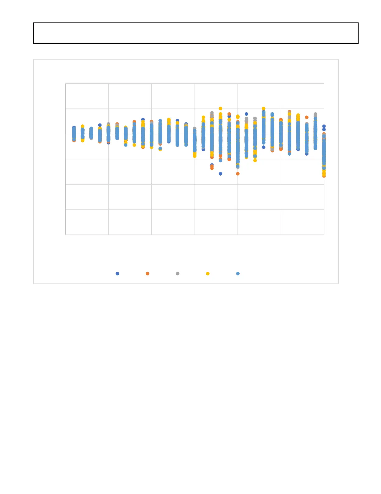
Figure 89 shows the phase error after synchronization of the two LOs, these are internal register reads but should be accurate.
Figure 89 Phase Error after synchronization between two LOs
-8
-6
-4
-2
0
2
4
0 500 1000 1500 2000 2500 3000
Phase [deg]
LO Freq [MHz]
Phase between LO1 and LO2
Chip1 Chip2 Chip3 Chip4 Chip5
 Loading...