UG-1828 Preliminary Technical Data
Rev. PrC | Page 98 of 338
Figure 94. RF LO Generation Diagram
RF PLL Loop Filter Recommendations
For optimal phase noise and EVM performance, a lookup table of RF PLL loop filter bandwidth settings is implemented in ADRV9001
firmware. ADRV9001 automatically selects best RF PLL loop filter configuration based on LO frequency. Alternatively, user can program
its own RF PLL loop filter bandwidth following instruction outlined in Loop Filter Configuration paragraph.
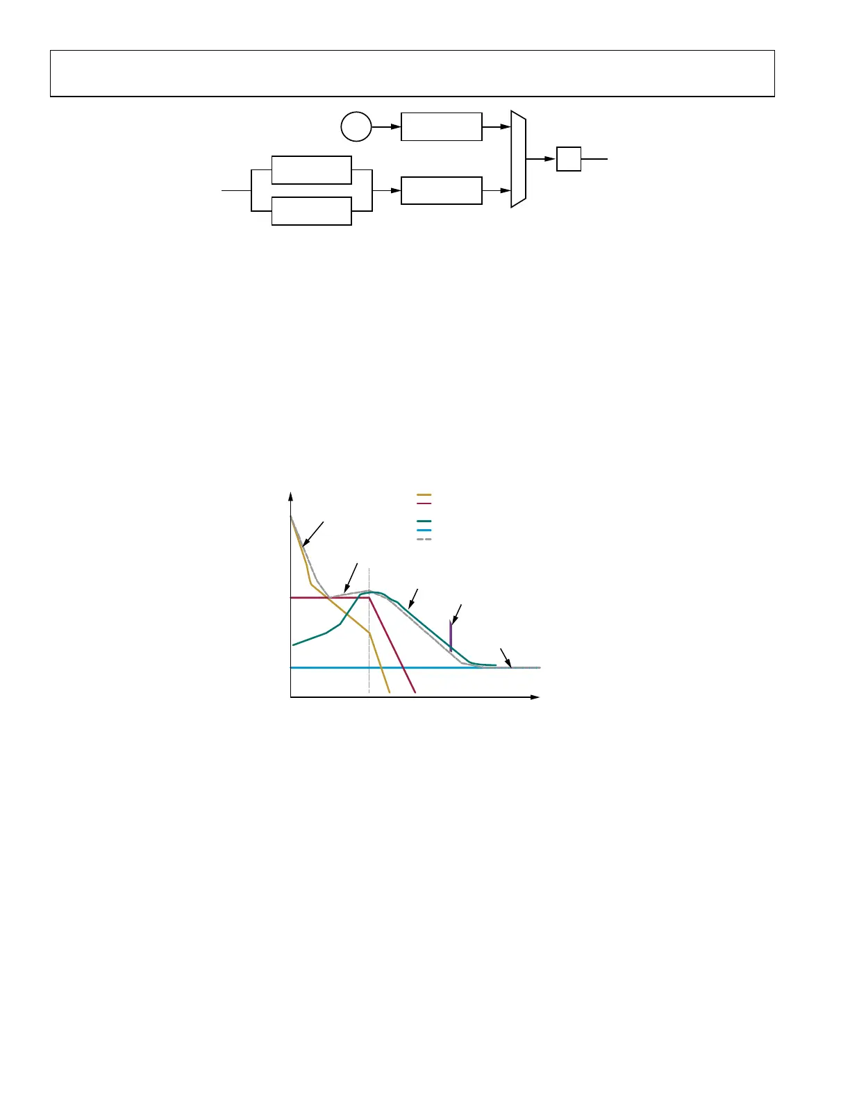
PLL Phase Noise
The Figure 95 shows the typical PLL phase noise contributors. For low offset frequencies reference clock dominates the phase noise, and
for high offset frequencies, VCO noise dominates the phase noise. User can optimize the phase noise by:
• Provide better reference clock source
• Provide higher reference clock frequency (PFD)
• Adjust loop filter bandwidth to trade-off between close-in band and far-out band noise
When changing the loop filter bandwidth, typically consideration is the wider the bandwidth, the better close-in band noise, but the
worse the far-out band noise. User should trade-off between the two to find the optimal setting for the specific application.
Figure 95. PLL Phase Noise Contributors
Following is an example that PLL phase noise is highly dependent on the PFD frequency (REF_CLK). With a higher PFD frequency, a
better phase noise can be achieved.
DIFFERENTIAL
EXT LO
/1, /2n,
n = 1,2,3,...255
/2 RF LO
SINGLE-ENDED
EXT LO
EXT LO IN±
/1, /2n,
n = 1,2,3,...255
RF
VCO
24159-078
F
LOOP
INPUT
REFERENCE
PHASE DETECTOR
AND CHARGE PUMP
AMPLITUDE
NOISE
VCO
–20dB/dec
SPUR
LOG F
OFFSET
PHASE NOISE
FREQUENCY OFFSET
INPUT REFERENCE NOISE
PHASE DETECTOR AND
CHARGE PUMP NOISE
VCO NOISE
AMPLITUDE NOISE
OVERALL PLL NOISE
24159-079
 Loading...