128
ION-B User Manual
TFLN
TFLN Visual Alarms
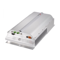
The TFLN front panel is provided with 6 LEDs (see right), showing status and alarm information.
LED signifi cance is reported on the above table.
Further information about alarm status is delivered by the ION-B Supervision System.
Note: In case the four TFLN optical output ports are not all connected to Remote Units, the
unused ports must be properly masked at commissioning in order to avoid spurious alarms
(please refer to LMT manual).
TFLN power supply
Each TFLN master optical TRX is supplied by the sub-rack backplane (12V).
The power consumption of each TFLN master optical TRX is 12W.
Warnings (to be read before TFLN installation)
Dealing with optical output ports
• The TFLN master optical TRX contains semiconductor lasers. Invisible laser beams may
be emitted from the optical output ports. Do not look towards the optical ports while
equipment is switched on.
Label LED colour Signifi cance
= Green Power supply status OK
Red
General TFLN failure, it might be:-
TFLN laser failure
- UL or DL amplifi er failure
- TFLN short circuit
1 Red
Low UL optical power received
from Remote Unit 1 (fault in
optical link 1 or Remote Unit 1
failure)
2 Red
Low UL optical power received
from Remote Unit 2 (fault in
optical link 2 or Remote Unit 2
failure)
3 Red
Low UL optical power received
from Remote Unit 3 (fault in
optical link 3 or Remote Unit 3
failure)
4 Red
Low UL optical power received
from Remote Unit 4 (fault in
optical link 4 or Remote Unit 4
failure)
2
4
1
=
3
Fig 4.3.2:
Visual alarms on the TFLN
Master Optical Transceiver.
Table 4.3.1:
Visual alarms on the TFLN
Master Optical Transceiver.
 Loading...