149MN024-010
TMPx-10
Description
The TMPx-10 Power Limiter monitors the downlink
input power and attenuates it by 10dB above
a predetermined set point. The threshold is
programmable through the Supervision System.
The TMPx-10 power limiter is available in two
versions, one for GSM 900 MHz / DCS 1800 MHz
applications, and the other for UMTS 2100MHz.
RF Ports
• 1 DL RF input port
• 1 DL RF output port
TMP Main Applications
The main applications of the TMP module is:
• Controlling the DL RF level coming from a
donor source in order to protect the system if
the level exceeds a specifi ed threshold.
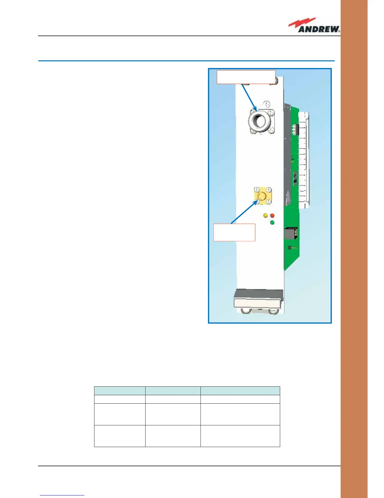
TMP Visual Alarms
The TMP front panel is provided with 3 LEDs
(please see fi g. 4.10.1) showing status and alarm
information. The LED meaning is reported in the table below.
Further information about alarm status is delivered by the ION-B Supervision System
4.10. Power Limiter TMPx-10
Label LED colour Meaning
Power Green Power supply status OK
Alarm Red
It can be:
- TMP power supply alarm
- RF input overdrive
Warning Yellow
It can be:
- temperature alarm
- no RF signal at the input port
DL RF input port
(from donor source)
DL RF output
port
(to master unit)
Fig. 4.10.1: The TMPx-10 Power Limiter
Table 4.10.1: LED alerts on the TMP front panel
 Loading...