106
ION-B User Manual
TPRN
The TPRN sub-rack provides sub-D 15 poles male connector, shown in Fig. 4.1.5
As highlighted in Table 4.1.4, this connector provides:
• 4 opto-isolated input ports which can be used to reveal any failure condition on external
PIN Name Meaning
1 Ground It is a ground terminal for digital inputs, i.e. for pin 2, 3, 9, 10.
2
Digital input n.1
(SW assignable)
This port can be used to monitor external equipment status. Once a default working
status has been assigned (through the Supervision System) to this input port, any
change is detected as a failure signal.
3
Digital input n.2
(SW assignable)
This port can be used to monitor external equipment status. Once a default working
status has been assigned (through the Supervision System) to this input port, any
change is detected as a failure signal.
4 Disconnected pin No meaning
5,6
Summary of
major alarms
These pins present an open circuit if a major alarm is active on the TPRN sub-rack or
on any module hosted in it.
7,8
Summary of
minor alarms
These pins present an open circuit if a minor alarm is active on the TPRN sub-rack or
on any module hosted in it.
9
Digital input n.3
(SW assignable)
This port can be used to monitor external equipment status. Once a default working
status has been assigned (through the Supervision System) to this input port, any
change is detected as a failure signal.
10
Digital input n.4
(SW assignable)
This port can be used to monitor external equipment status. Once a default working
status has been assigned (through the Supervision System) to this input port, any
change is detected as a failure signal.
11 Disconnected pin No meaning
12,13
Digital output n.1
(SW assignable)
These pins are terminals of an output port (output relay 1), which can be driven
through the Supervision System. The output port can be set to “open” or “close”
condition. These 2 statuses can be used to pilot any external device connected to
subD-15 connector.
14,15
Digital output n.2
(SW assignable)
These pins are terminals of an output port (output relay 2), which can be driven
through the Supervision System. The output port can be set to “open” or “close”
condition. These 2 statuses can be used to pilot any external device connected to
subD-15 connector.
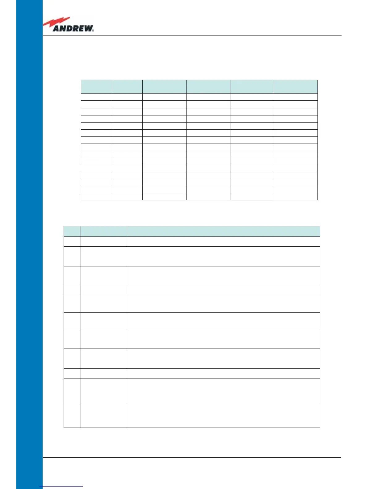
Address
(Dec)
Address
(Bin)
Dip-switch 1 Dip-switch 2 Dip-switch 3
Dip-switch 4
1 0001 ON OFF OFF OFF
2 0010 OFF ON OFF OFF
3 0011 ON ON OFF OFF
4 0100 OFF OFF ON OFF
5 0101 ON OFF ON OFF
6 0110 OFF ON ON OFF
7 0111 ON ON ON OFF
8 1000 OFF OFF OFF ON
9 1001 ON OFF OFF ON
10 1010 OFF ON OFF ON
11 1011 ON ON OFF ON
12 1100 OFF OFF ON ON
13 1101 ON OFF ON ON
14 1110 OFF ON ON ON
Reserved 1111 ON ON ON ON
Table 4.1.3: Dip-switches address settings
Table 4.1.4: Functional description of pins provided by sub-D male connector
 Loading...