24
ION-B User Manual
2.5. Block Diagrams
In order to better understand the functionalities of the different units and modules, some block
diagrams of the ION-B system are presented here.
The core of an ION-B system is the ION-B master unit, which generally develops through a
passive section (providing Level adjustments, Signal splitting/combining, and Band coupling),
followed by an Electrical/Optical conversion (allowing the signal to be distributed through
fi beroptic cables to the TFAx Remote Units).
Simple and unobstrusive ION-B installations can be developed through the TPRF31 fast
MiniRacks, which allows a great deal of installation solutions, such as:
- hosting two electrical/optical transceivers, while developing external passive combining
- hosting one electrical/optical transceiver, plus one ION-B interface card (providing splitting/
combining , band coupling or level adjusting).
Please note that more TPRF31 modules can be combined to achieve a more complex, space-
saving system confi guration.
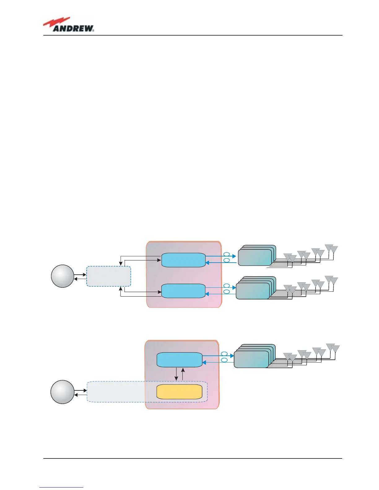
Tipical ION-B confi gurations based on a single TPRF31 Fast MiniRack are shown in fi g. 2-13.
ION-B Fast Minirack
BTS
Remote Unit
TFAx
Remote Unit
TFAx
TFLN
Master Optical Trx
TFLN
Master Optical Trx
+
External
splitting/combining
section
ION-B Fast Minirack
BTS
Remote Unit
TFAx
TFLN
Master Optical Trx
ION-B passive card
(either splitting/combining
or level adjusting
Splitting/combining section
(a)
(b)
Fig. 2.13: ION-B confi gurations based on a TPRF31 Fast MiniRack: (a) Confi guration hosting 2 TFLN optical
transceivers; (b) Confi guration hosting 1 TFLN optical transceiver and 1 splitting/combining card
 Loading...