46
ION-B User Manual
TFAM
Case B
RF ports:
• 2 RF antenna ports, transmitting/receiving signals to/from distributed antennas. RF
antenna ports are duplexed N-female connectors. These RF ports can be connected
to the antennas either directly (ie. through RF jumper cables) or through splitters, thus
allowing more antennas to be fed. Unused RF ports have to be terminated with a 50 Ω
load.
• 1 RF auxiliary input and 1 auxiliary output (designed to receive and transmit additional
signals). Auxiliary input and output ports are SMA-female connectors.
Optical ports:
• 1 optical output port, transmitting UL signals to TFLN master optical TRX
• 1 optical input port, receiving DL signals from TFLN master optical TRX
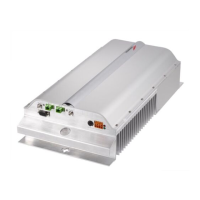
Visual Alarms:
Two control LEDs are provided on the TFAx front side (Fig. 3.3.2). The green LED indicates the
power supply status, while the red LED indicates any major Remote Unit failures (please refer to
Table 3.4).
Led colour Meaning
Red
Low optical power at DL input
and/or RF amplifi er failure
Green Power supply OK
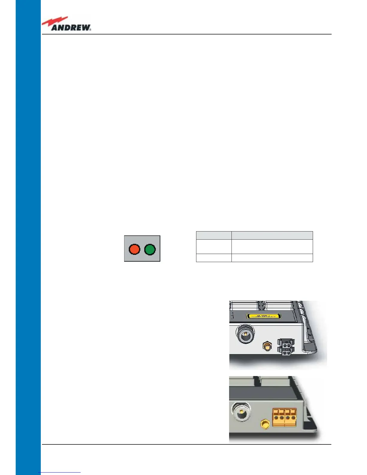
Dry Contact Alarms:
TFAx is provided with two dry contact inputs which
can be connected (through .062” MOLEX plugs)
to any external device. The alarm information
regarding this external device is able to be signalled
through the red LED of the TFAx LED panel and
displayed on the Supervision System in this way.
Figure 3.3.3 - Dry contacts for external alarms on (a)
Case B Remote Unit and (b) case-B Power Remote
Unit
(a)
(b)
Figure 3.3.2 - LED alarms on
the upper-front side of Case
B Remote Units (including Power version)
Table 3.3.1 - Description of the LEDs
of Case-B remote unts
 Loading...