36
ION-B User Manual
TFAM
Case A
APC adapters open, as they attract dirt. Unused optical connectors must always be
covered with their caps.
• Do not touch the connector tip. Clean it with suitable material before inserting each
connector into its sleeve. If connector tips require cleaning, use only pure ethyl alcohol.
TFAx Case A installation
The Case B Remote Unit is able to be fi xed to walls, false ceilings or other fl at vertical surfaces,
either directly or through a TKA04 installation kit (optional).
Installing a Case A Remote Unit WITHOUT the TKA kit
The TFAx kit includes:
1. a Remote Unit TFAx
2. a TPSN external power supply adapter (86 to 264 Vac or -72 to -36 Vdc, according to the
chosen model)
3. a VDE connector or a -48 Vdc plug (according to the chosen model)
The TKA04 kit includes:
A. four screw anchors (fi xing the wall bearing to the wall)
B. fi ve screw anchors (fi xing the TFAx Case A to the wall bearing)
C. a wall mounting box (wall bearing + cover)
D. a splice holder
Please consider these guidelines in order to choose the correct positioning of the Remote Unit
and of its power supply:
• Under no circumstances should any piece of equipment be affected by the heat
(a)
(b)
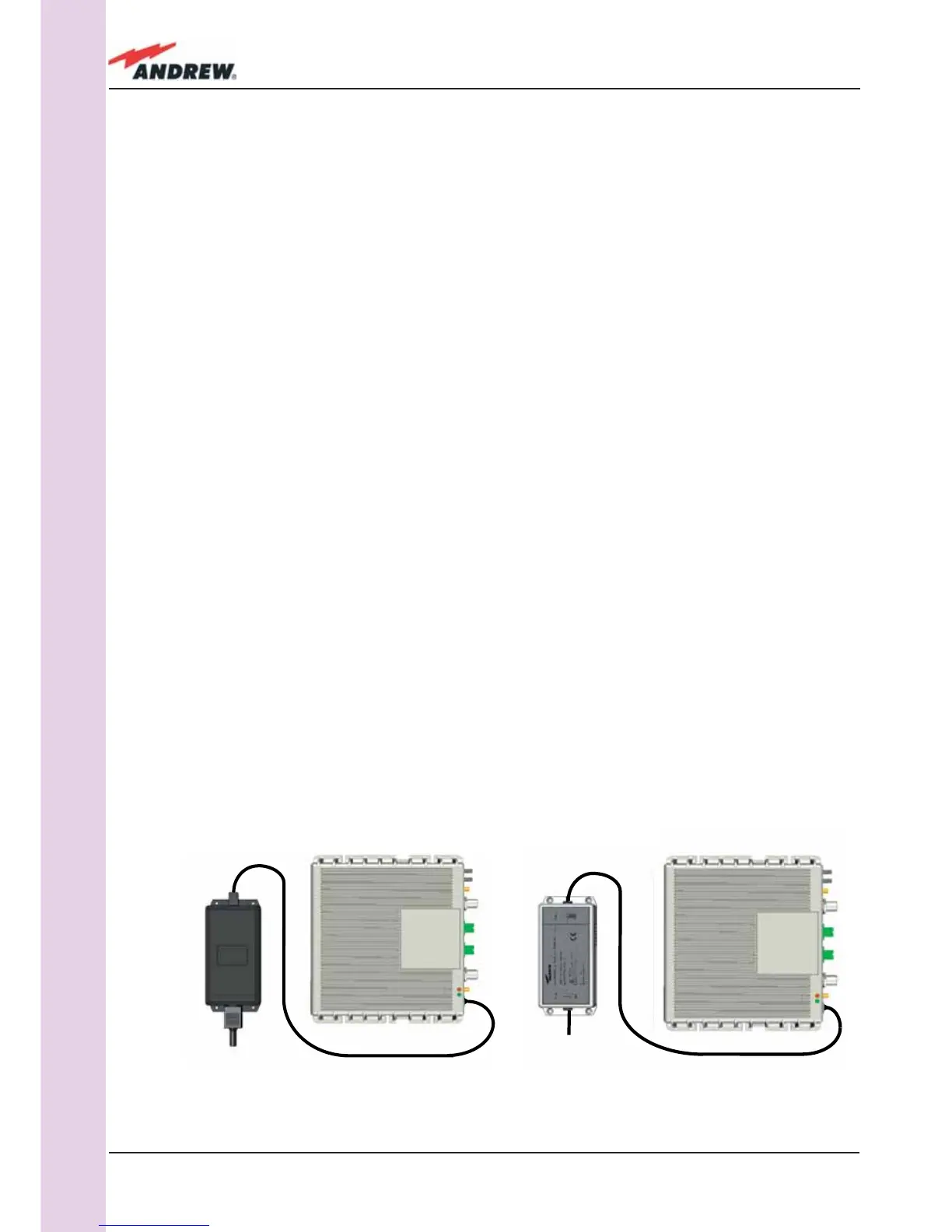
Figure 3.2.6: Example of proper mounting confi guration, which assures proper heat dissipation. Note that the
Remote Unit and its power supply adapter are mounted side-by-side, and the power supply adapter has the
socket downwards. The Figures refer to a 90/264 vac TFAx Case A (an) and to a -36/-72 Vdc TFAx Case A (b).
 Loading...