37MN024-010
TFAM
Case A
created by any other piece. The Remote Unit and its external power supply should be
mounted so as to avoid reciprocal heating. Side-by-side confi guration is suggested (Fig.
3.2.6 a,b)
• Remote Units are provided with cooling fi ns which allow the optimization of heat
dissipation. In order for them to function properly, the mounting environment should allow
for the necessary air changeover
• It is strongly recommended not to mount the external power supply on a horizontal
surface because this position does not allow heat dissipation. External power supplies
must be mounted on vertical surfaces.
• In order to assure proper heat dissipation, external power supplies must be mounted in a
vertical position with the power socket downwards (see Fig. 3.2.7 a,b).
Once you have chosen a location for the Remote Unit, please follow these instructions:
1. In order to install the M4 screw anchors (not included) which hold up the TFAx Remote
Unit, drill into the wall according to the proper layout shown in Fig. 3.2.9.
2. Fix the TFAx to the wall by fi rmly tightening the screws into the anchors.
3. In order to install the M4 screw anchors (not included) which hold up the power supply
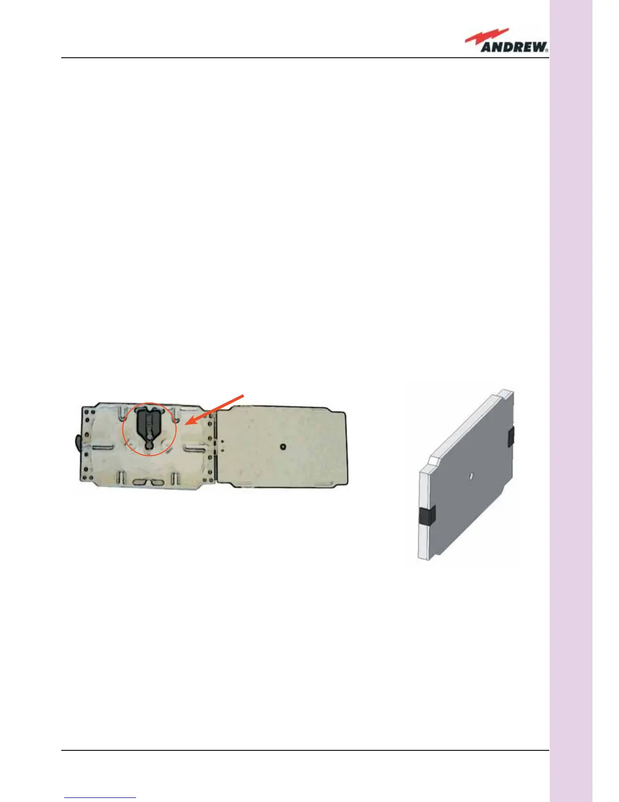
Fig. 3.2.7. (a) inside of the Splice Tray, with the Splice
Holder positioned properly; closed splice tray (b)
(a)
(b)
SPLICE HOLDER
external adapter, drill into the wall according to the proper layout of your power supply,
shown in fi g.3.3.10b
4. Fix the external power supply adapter to the wall by fi rmly tightening the screw into the
anchors.
5. Fix the splice holder inside the splice tray (not included) See Fig. 3.2.7 a,b.
6. Splice the optical fi bres and close the splice tray. While handling the fi bers, be careful not
to bend them.
7. Fix the splice tray beside the Remote Unit.
8. Connect the external adapter to the TFAx Remote Unit with the proper cable.
9. If the Remote Unit is -48 Vdc powered, use the -48 Vdc plug (included) in order to
 Loading...