151MN024-010
TMPx-10
}
}
GSM 900 MHz
DCS 1800 MHz
TMP Installation
The TMP power limiter can be accomodated in any of the 12 slots of a TPRN active sub-rack.
Note: In case a new TMP module has to be installed in a still working Master Unit, switch off the
sub-rack before inserting the plug-in TMP module
1. Unpack the kit, which includes
ÿ 1 TMP
ÿ 1 RF jumper (SMA-m), 35cm
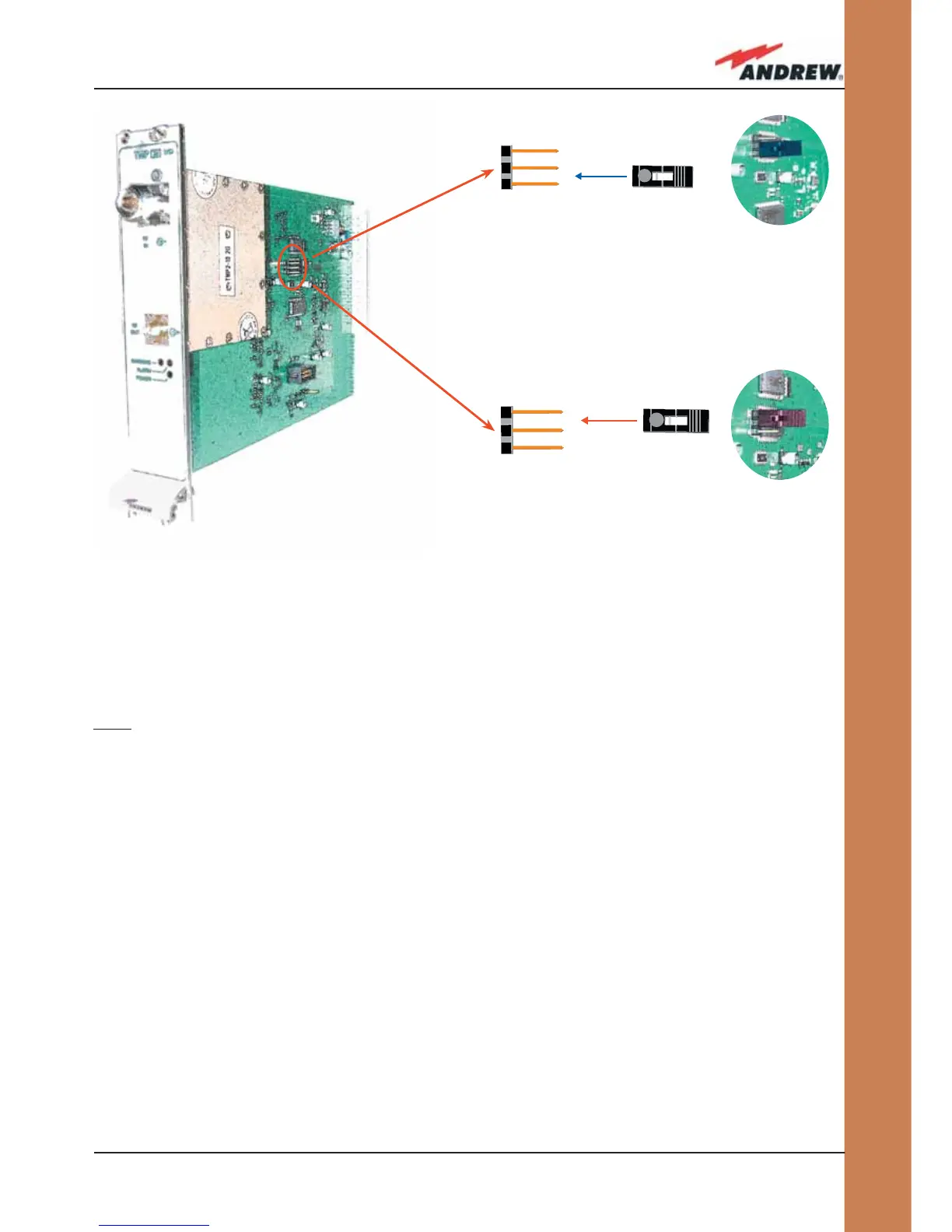
If your card is a TMP2-10, take care to set the 2-pin jumper in the proper working
position (GSM 900 MHz or DCS 1800 MHz), according to the fi gure
2. Carefully insert the TMP module in any of the TPRN sub-rack slots and tighten the 4 screws
on the front corners.
3. Connect RF cables according to what has been planned by the designer. Use an
appropriate torque wrench to fi x each cable to their relevant ports.
4. Switch on the sub-rack. As you switch on the system, carefully refer to the TFLN Start-up
section.
Fig. 4.10.2:
Proper setting of the 2-pin jumper in the TMP2-10 Power
Limiter: (a) GSM 900 MHz band ; (b) DCS 1800 MHz band.
(a)
(b)
 Loading...