38
ION-B User Manual
TFAM
Case A
connect the external adapter to the -48 Vdc supply (Fig. 3.2.6 b). If the Remote Unit
is 90/264 Vac-powered, fi x the 90/264 Vac plug (included) onto a power cord (not
included), and use this cable to connect the external adapter to the mains (Fig. 3.2.6 a).
10. Connect the antenna RF cables to the RF antenna ports. Connect the UL and DL optical
connectors.
11. Once the installation is fi nished, please follow the section “TFAx Case A Start-up” in order
to carry out a proper system start up.
Installation of the Case A Remote Unit WITH the TKA04 installation kit
The TFAx Case A kit includes:
1. a Remote Unit TFAx
2. a 50 Ω load
3. a TPSN external power supply adapter (86 to 264 Vac or -72 to -36 Vdc, according to the
chosen model)
4. a VDE connector or a -48 Vdc plug (according to the chosen model)
The TKA04 kit includes:
A. four screw anchors (fi xing the wall bearing to the wall)
B. fi ve screw anchors (fi xing the TFAx Case A to the wall bearing)
C. a wall mounting box (wall bearing + cover)
D. a splice holder
Please consider these guidelines carefully in order to decide the proper positioning of the
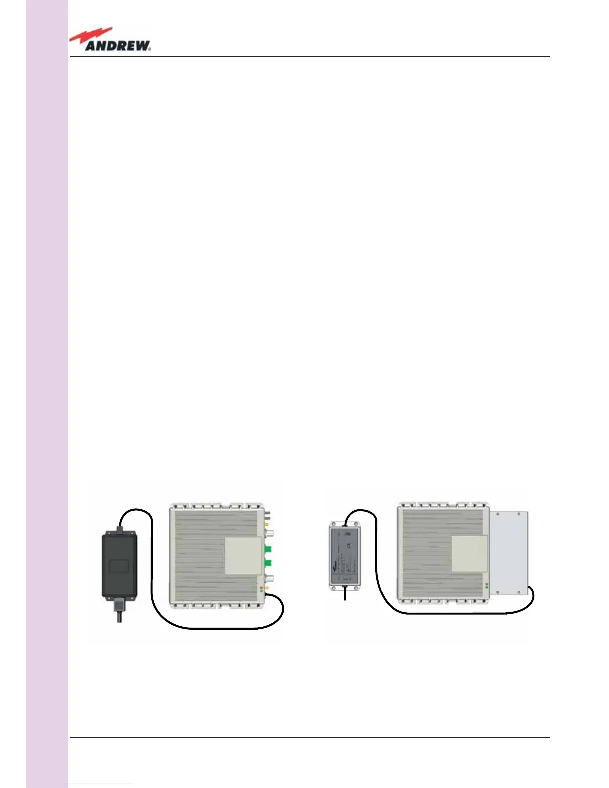
Figure 3.2.8:
Example of proper mounting confi guration, which assures proper heat dissipation. Note that the Remote Unit and
its power supply adapter are mounted side-by-side, and the power supply adapter has the socket downwards.
The Figures refer to a 90/264 vac TFAx Case A (a) and to a -36/-72 Vdc TFAx Case A (b), respectively.
(a)
(b)
 Loading...