88
ION-B User Manual
TFAM
Case F
External alarms
Case F architecture does not provide any external alarms control.
Power supply:
Case-F Remote Unit is available in two versions: one feeded by universal mains (85 to 265 Vac),
the other by negative power supply (-72 to -36 Vdc): in fi gure 3.6.3, the 85/220 Vac connector
and the -72/-36 Vdc connector are described. Power feeder is always internal. The power
cable is always included in the Case-F Remote Unit kit.
RF ports:
• 1 RF antenna port, transmitting/receiving signals to/from distributed antennas. This RF
antenna port is a duplexed N-female connectors. The port can be connected to the
antenna either directly (ie. through RF jumper cables) or through splitters, thus allowing
more antennas to be fed.
• 1 RF auxiliary input and 1 RF auxiliary output (designed to receive and transmit additional
signals). Auxiliary input and output ports are SMA-female connectors.
Optical ports:
• 1 optical output port, transmitting UL signals to TFLN master optical TRX;
• 1 optical input port, receiving DL signals from TFLN master optical TRX.
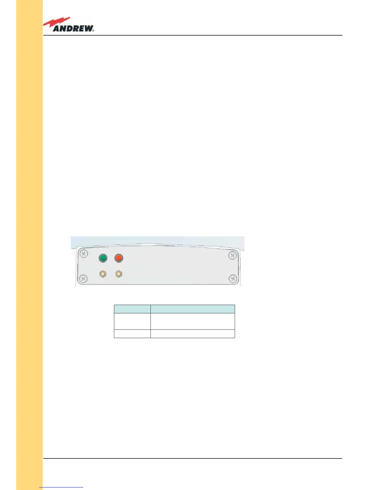
Visual alarms:
Two control LEDs are provided on the Case-F upper side (fi g. 3.6.2).
The green LED describes the power supply status, while the red LED describes the major
Remote Unit failures (Table 3.6.1).
Led colour Meaning
Red
Low optical power at DL input
and/or RF amplifi er failure
Green Power supply OK
Figure 3.6.2: LED panel on
the Case-F Remote Unit
Table 3.6.1: LED panel on
the Case-F Remote Unit
 Loading...