131MN024-010
TFLN
TFLN Start-Up
Before the Master Unit is switched on, make sure that:
• all necessary modules have been inserted into the Master Unit
• the modules have been connected each other by RF jumpers, according to what has
been planned in the system design
• every TFLN master optical TRX has been connected to the relevant Remote Units
• each Remote Unit has been connected to its coverage antenna
• the remote supervision unit, if present, has been connected to the Master Unit
• different Master Units are connected to each other via bus RS485
Following this, the Master Unit itself can be turned on, making sure to turn on all the Remote
Units fi rst,
Once the Master Unit has been switched on, the behaviour of the TFLN at system start-up is
able to be summarized with the following steps:
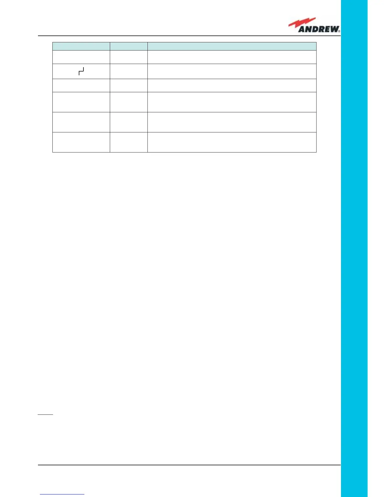
1. When the Master Unit is turned on, all six LEDs on the TFLN front panel remain lit for a
couple of seconds. After that, the green LED remains lit (indicating proper power supply)
while the other LEDs indicate the master optical TRX status, according to the following
table.
Note: If the unused optical ports of the TFLN haven’t been masked through the LMT yet,
corresponding LEDs will be lit. If this is the case, wait for the end of step 3 (discovery phase)
then use the LMT to mask them (please refer to relevant handbook)
2. About 10 seconds after the system has been switched on, the TFLN module begins a
Label LED colour Status
= Green
ON
(power supply is on)
Red
OFF
(no major failure affects TFLN operations)
1 Red
OFF
(no major failure affects corresponding Remote Unit or UL connection)
2
Red
OFF
(no major failure affects corresponding Remote Unit or UL connection)
3
Red
OFF
(no major failure affects corresponding Remote Unit or UL connection)
4 Red
OFF
(no major failure affects corresponding Remote Unit or UL connection)
Table 4.3.2: LED alerts on the TFLN front panel
 Loading...