76
ION-B User Manual
TFAM
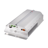
Case R2
APC adapter open, as they attract dirt. Unused optical connectors must always be
covered with their caps.
• Do not touch the connector tip. Clean it with a proper tissue before inserting each
connector into the sleeve. In case connector tips need to be cleaned, use pure ethyl
alcohol.
TFAx Case-R2 installation
Each Case-R2 Remote Unit kit includes:
• 1 Case-R2 Remote Unit;
• 1 power supply cable (85 to 264 Vac or -48Vdc, depending on the power supply which
has been chosen);
• 1 pair of mounting plates;
• 1 screw kit, including four hexagonal-head screws and a torque key.
The operations which need to be carried out in order to perform a proper installation of the
Case-R2 Remote Unit are hereby described:
The Cabinet-R2 Remote Unit has to be mounted with heat-dissipation fi ns in vertical position.
The suggested installation layout is shown in Figure 3.5.5a, with the external power supply
mounted side by side to the Remote Unit, using a common screw anchor to support both the
Remote Unit’s right side and the power supply’s left wing.
An external splice box (not included) may be mounted side by side to the power supply or to
the Remote Unit, sharing an anchor with one of them (see pict 3.5.5g).
1 – Drill the wall to install the four M6 screw anchors (not included) according to the layout
shown in Fig. 3.5.5b.
As an alternative, you can choose to install your power supply conveniently close to the
Remote Unit.
2 – Insert the four M6 screw anchors in the holes, and fi x the power supply to the wall.
If you planned to use a common screw anchor to support both the Remote Unit and the
external power supply, take care not to screws this anchors till you fi xed the Remote Unit
(Fig. 3.5.5c).
3 – Fix the Remote Unit to the wall and tighten the 4 screw anchors (Fig. 3.5.5d)
4 - Fix the splice holder (not included) inside a splice tray like the one shown in Fig. 3.5.5e (not
included).
Make the optical splices and close the splice tray (Fig. 3.5.5f).
Place the splice tray inside a splice box (not included), and mount the splice box beside
the Remote Unit. The suggested installation position is side by side to the power supply or
 Loading...