80
ION-B User Manual
TFAM
Case R2
to the Remote Unit, using one of their M6 anchors already installed to support the splice
box as well (please see Fig. 3.5.5g).
NOTE: Take care not to bend the fi bers too much.
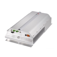
5 - Now connect the RF cables, the optical connectors, and the power supply connector to
the Remote Unit (Fig. 3.5.5h).
Take care to connect UL and DL fi bers properly (Fig. 3.5.5i ).
After the Remote Unit has been properly cabled, insert the power plug in the external
power supply adapter, so as to connect it to the mains.
6 - A fi ber protection can be placed around DL optical fi bers (Fig. 3.5.5l ).
TFAx Case R2 start-up
Before the Case-R2 Remote Unit is switched on, make sure that:
• the modules hosted in the master unit have been connected each other with RF
jumpers, according to the system design
• every TFLN master optical Trx has been connected to its Remote Units
• each Remote Unit has been connected to its coverage antennas
For a correct system start-up, all the Remote Units have to be switched on before the
master unit.
Once the Cabinet-R2 Remote Unit has been switched on, its behaviour could be checked by
unscrewing the four hexagonal screws (see fi g on the sides of the case-F), removing the cover,
and looking at the control LEDs. When the system starts-up, their status can be summarised as
per the following steps.
1. When the Remote Unit is turned on, both the LEDs turn on for a couple of seconds.
2. After that, the unit green LED remains on (thus indicating proper power supply), while the
red LED switches off as soon as the TFLN master unit is turned on (meaning that DL optical
power is OK and no alarms are present).
3. Once the TFLN master unit has been switched on, the status of both LEDs have to be the
one reported in table 3.5.1. If the red LED remains on, please refer to the troubleshooting
section.
4. Once it has been switched on, the Remote Unit starts working correctly. Anyway, in
order to be recognized by the supervision management system, it is necessary for the
corresponding TFLN master optical TRX to carry out the discovery phase (please refer to
Supervision System Manual for more details). During this phase, (whose duration depends
on the system complexity, and which can last at max. 4min) the TFLN LED blinks. Do not
connect/disconnect any cable or any piece of equipment during the discovery phase!
This may result in no identifi cation of the Remote Unit.
 Loading...