Chapter 5 — Component Replacement 5-9 Low Band Switch
MN469xC Series Multiport Test Set MM PN: 10410-00730 Rev. D 5-9
5-9 Low Band Switch
Assemblies: ND70079<R> or 3-ND70079<R> – A4, A5, A6, A7
This section provides procedures for removing and replacing each Low Band Switch in the test set. There are
four Low Band Switches, A4, A5, A6 and A7. In Figure 5-2 on page 5-3 above, refer to the A4, A5, A6, and A7
engineering references. The replacement procedures for each module vary slightly.
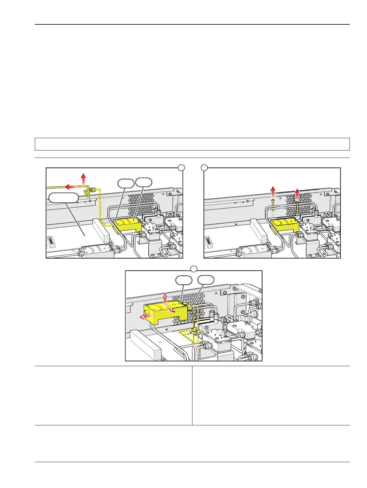
A4 Replacement
1. Remove the top cover from the test set.
• Refer to Section 5-3.
2. Replace the A4 module as illustrated in Figure 5-8.
Note Use Anritsu 01-201 Torque Wrench to tighten all RF connectors when installing the module.
1. Disconnect the RF cable from the J1 connector of the
A4 module and the Rear Panel.
Note: The GPIB–Parallel Interface Board may
have to be removed in order to remove the A4 RF
cable. See Section 5-5 for GPIB board removal.
2. Remove the two Phillips mounting screws from the
module.
3. Disconnect the two connectors from J2 and J3
connectors, then disconnect the control cable from
the module side and remove the module.
4. Installation is the reverse of removal.
Figure 5-8. A4 Low Band Switch Replacement
1
2
3
a
a
b
b
c
c
A4
J1
J2
J3
See Note

 Loading...