Chapter 5 — Component Replacement 5-15 Port Coupler
MN469xC Series Multiport Test Set MM PN: 10410-00730 Rev. D 5-23
A15 Replacement
1. Remove the top cover from the test set as instructed in Section 5-3.
2. Remove the A10 Diplexer Assembly as instructed in Section 5-13.
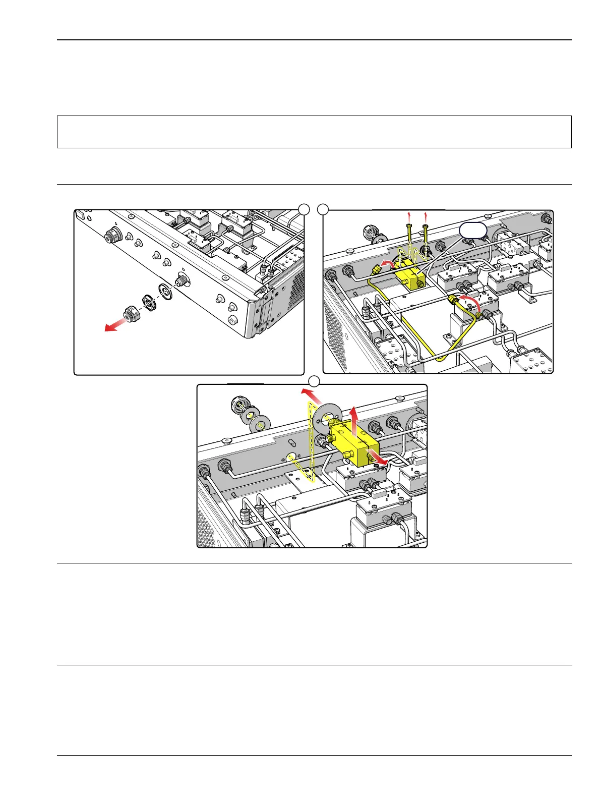
3. Replace the A15 Port Coupler Assembly as illustrated in Figure 5-22.
Note
De-soldering of the DC Bias wires from the A10 Diplexer Assembly is not required. Use Anritsu
01-201 Torque Wrench to tighten all RF connectors when installing the module.
1. Remove the Test Port Connector, the Port Connector Nut, and the Thrust Washer from the front panel.
2. Disconnect the RF cable from the A15 coupled port. Use a right angle Phillips screwdriver to remove the two
mounting screws that secure the Port Coupler to the bracket. (If a right angle driver is not available the front
panel must be removed to gain access to forward screw on the coupler.)
3. Remove the A15 Coupler from the chassis and separate the spacer from the front of the coupler.
4. Installation is the reverse of removal. When installing the test port connector, torque to 15 lbfꞏin using a torque
wrench.
Figure 5-22. A15 Port Coupler Assembly

 Loading...