Chapter 5 — Component Replacement 5-10 Low Band Bridge
MN469xC Series Multiport Test Set MM PN: 10410-00730 Rev. D 5-13
5-10 Low Band Bridge
Assembly: ND70078<R> or 3-64016<R> – A20, A21
This section provides a procedure for removing and replacing the Low Band Bridges in the test set. There are
two Low Band Bridges, A20 and A21. Refer to Figure 5-2 on page 5-3 for physical location on the chassis.
A20, A21 Replacement
1. Remove the top cover from the test set as instructed in Section 5-3.
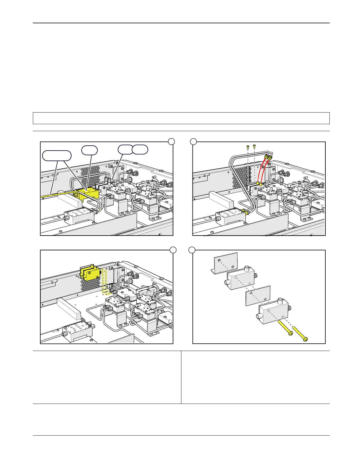
2. Replace the A20 or A21 module as illustrated in Figure 5-12.
Note Use Anritsu 01-201 Torque Wrench to tighten all RF connectors when installing the module.
1. Remove the A4 low band switch. See “A4
Replacement” on page 5-9. See Section 5-5 for GPIB
board removal.
2. Disconnect the two RF cables from the JB connector
on each bridge and rotate them out of the way, then
remove the two bracket mounting screws. (The JB
connector is the one facing upward).
3. Remove the A20/A21 assembly
4. Remove and replace the A20 or A21 module as
shown.
5. Installation is the reverse of removal.
Figure 5-12. A20/A21 Low Band Bridge Replacement

 Loading...