5-12 High Band SPDT Switch Assembly Chapter 5 — Component Replacement
5-16 PN: 10410-00730 Rev. D MN469xC Series Multiport Test Set MM
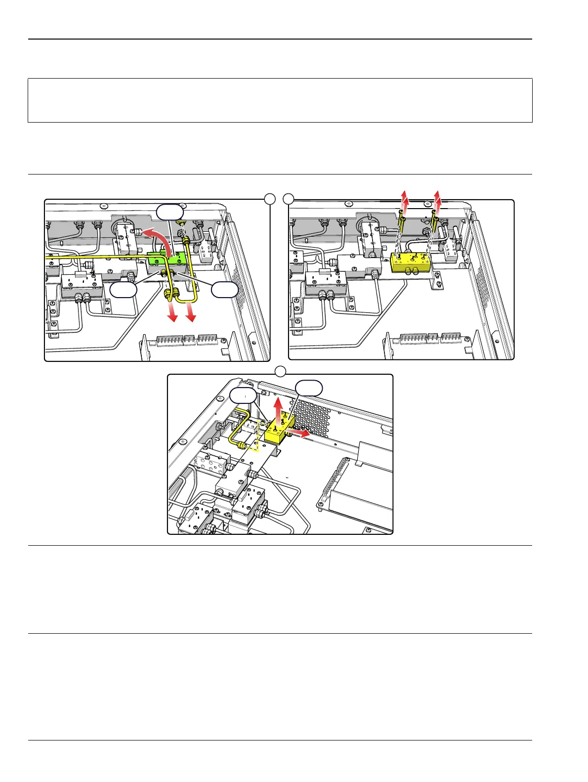
A13 Replacement
1. Remove the top cover from the test set as instructed in Section 5-3.
2. Replace the A13 Switch Assembly as illustrated in Figure 5-15.
Note
For this procedure, a right angle wrench is required to loosen the RF cable connectors attached at
the front panel. Use Anritsu 01-201 Torque Wrench to tighten all RF connectors when installing the
module.
1. Remove the Switch Control Board and the 3 standoffs from the A12 switch per the procedure in Section 5-11,
then disconnect and remove the RF cables between J2 and J3 of A13 and the front panel connector. Use a right
angle wrench to loosen the connector attached at the front panel.
2. Remove the four A13 switch mounting screws from the bracket.
3. Disconnect the RF cable from J1 of A13 and lift the module out of the chassis.
4. Installation is the reverse of removal.
Figure 5-15. A13 High Band SPDT Switch Assembly
1
2
3
A13
A13
J1
J2
J3

 Loading...