5-12 High Band SPDT Switch Assembly Chapter 5 — Component Replacement
5-18 PN: 10410-00730 Rev. D MN469xC Series Multiport Test Set MM
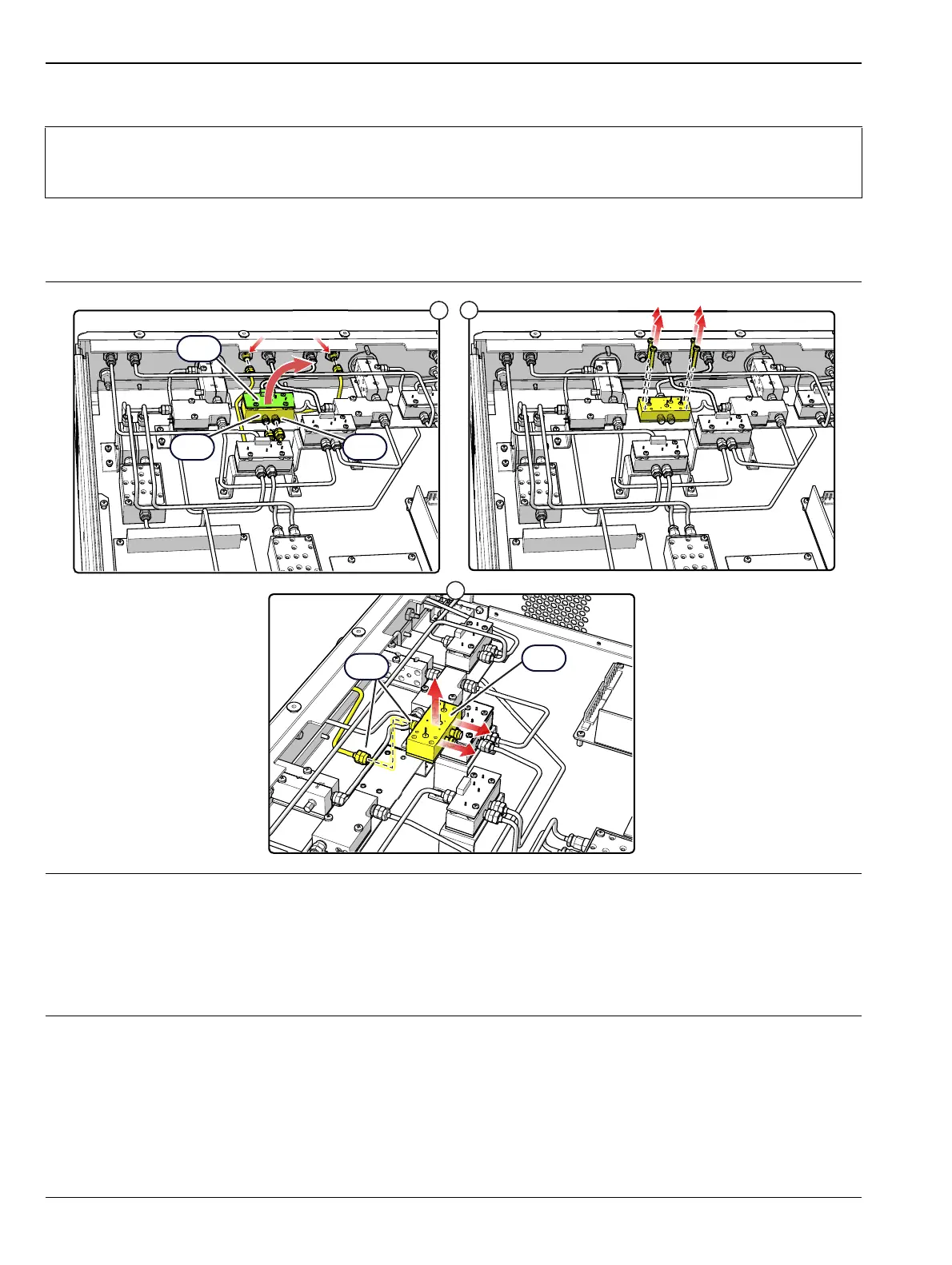
A19 Replacement
1. Remove the top cover from the test set as instructed in Section 5-3.
2. Replace the Switch Assembly as illustrated in Figure 5-17.
Note
For this procedure, a right angle wrench is required to loosen the RF cable connectors attached at
the front panel. Use Anritsu 01-201 Torque Wrench to tighten all RF connectors when installing the
module.
1. Remove the Switch Control Board and the 3 standoffs from the A19 switch per the procedure in Section 5-11,
then disconnect the RF cables from J2 and J3 of A19 and their respective front panel connectors. If needed, use
a right angle wrench to loosen the connectors attached at the front panel.
2. Remove the four A13 switch mounting screws from the bracket.
3. Disconnect the RF cable at A13-J1 to remove the module.
4. Installation is the reverse of removal.
Figure 5-17. A19 High Band SPDT Switch Assembly

 Loading...