Chapter 5 — Component Replacement 5-6 Rear GPIB Connector PCB Replacement
MN469xC Series Multiport Test Set MM PN: 10410-00730 Rev. D 5-5
5-6 Rear GPIB Connector PCB Replacement
Assemblies: 2000-989 or 3-2000-989
This section provides a procedure for removing and replacing the Rear Panel GPIB Connector PCB in the test
set.
1. Remove the top cover from the test set. Refer to Section 5-3 “Removing the Covers” on page 5-2.
2. Remove the board as illustrated in Figure 5-4.
Note
The Rear Panel GPIB Connector PCB Assembly is a part of the GPIB-Parallel Interface PCB
Assembly Replacement Kit, part number 2000-989.
Note Ensure that the two jumper wires are installed as shown in Figure 5-5 on page 5-6.
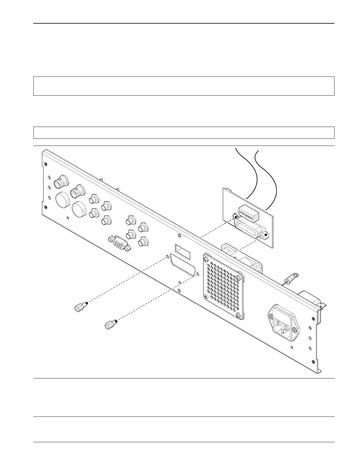
1. Disconnect the ribbon cable from the GPIB-Parallel Interface PCB Assembly. Refer to Figure 5-3.
2. Use an adjustable spanner wrench to un-screw the two hex nuts from the rear panel.
3. Remove the GPIB Connector PCB Assembly from the rear panel. Refer to Figure 5-4.
4. To replace the GPIB Connector PCB Assembly, reverse the order of the removal procedure.
Figure 5-4. GPIB Connector PCB Assembly Removal

 Loading...