Chapter 5 — Component Replacement 5-13 Diplexer Assembly
MN469xC Series Multiport Test Set MM PN: 10410-00730 Rev. D 5-19
5-13 Diplexer Assembly
Assemblies: 74277<R>/3-74277<R> or 74278<R>/3-74278<R> – A8, A10
This section provides a procedure for removing and replacing the two Diplexer Assemblies A8, and A10. Refer
to Figure 5-2, “Location of Major Components and Subassemblies” on page 5-3.
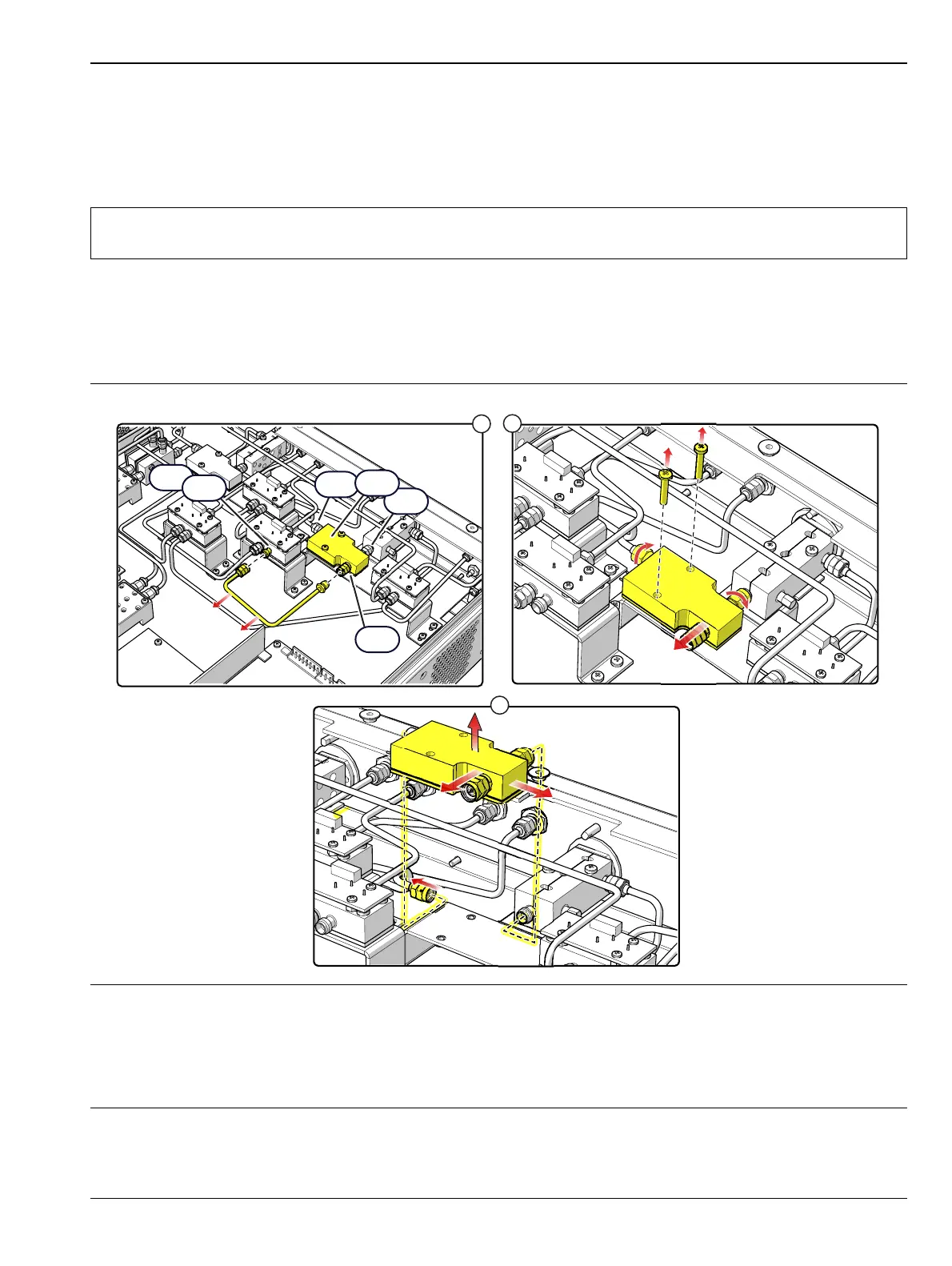
A8 Replacement
1. Remove the top cover from the test set as instructed in Section 5-3.
2. Replace the Diplexer Assembly as illustrated in Figure 5-19.
Note
The DC bias leads must be desoldered from the module prior to removal. Use Anritsu 01-201 Torque
Wrench to tighten all RF connectors when installing the module.
1. Remove the RF cable that connects between J3 of the Diplexer A8 and J3 of Switch A12.
2. Remove the four (4) A8 mounting screws, loo os en the J2 RF connector nut between A8 and A14, then gently
pry the module away from A14 while loosening the RF cable nut at J1.
3. Desolder the DC Bias wires from A8 and then remove it from the chassis.
4. Installation is the reverse of removal.
Figure 5-18. A8 Diplexer Assembly

 Loading...