Installation 9 (36)
3.4 Connector
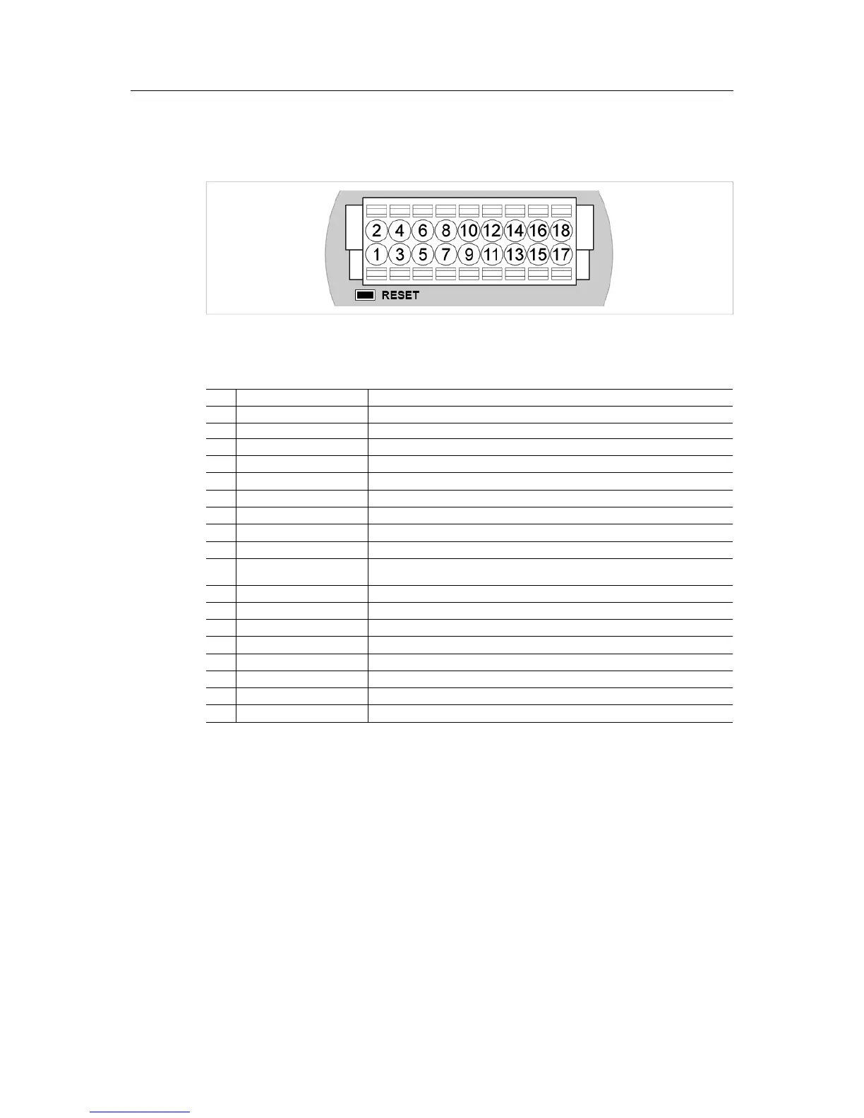
The 18-pin connector is common for all models of the Anybus Wireless Bolt. Some pins may
have a different function depending on model. Unused pins should not be connected.
The location of the RESET button can be used as a reference for the pin numbering when the
connector is attached to the Wireless Bolt. Pin 1 will be the pin closest to the button.
Pin Name
Description
1 VIN
Power + (9–30 V)
2 GND Power Ground
3 DI
Digital input + (9–30 V)
4
DI_GND Digital input ground
5
ETN_RD+ Ethernet receive + (white/orange)
6
ETN_RD- Ethernet receive - (orange)
7
ETN_TD- Ethernet transmit - (green)
8
ETN_TD+ Ethernet transmit + (white/green)
9
RS485_B
RS-485 B Line
10 FE/Shield
Ethernet:
Serial:
Functional Earth
Functional Earth and Shield
11
RS232_TXD
RS-232 Transmit
12
RS485_A/RS232_RXD
RS-485 A Line / RS-232 Receive
13
RS232_RTS RS-232 Request To Send
14
RS232_CTS
RS-232 Clear To Send
15
ISO_5V
Isolated 5 V for serial interface
16
ISO_GND
Isolated Ground for serial interface
17
CAN_L
CAN Low
18
CAN_H CAN High
Note:
• The Ethernet wire colors refer to the T568A standard.
• If using a shielded Ethernet cable the shield must be unconnected.
• RS-232 and RS-485 cannot be used at the same time.
• Use termination for RS-485 and CAN when required.
Anybus
®
Wireless Bolt
™
User Manual SCM-1202-007-EN 2.5