TOP VIEW
A
C
B
15” MINIMUM
CLEARANCE
FOR FILTER
(EITHER SIDE)
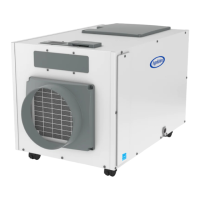
FIGURE 9: FILTER ACCESS CLEARANCE
DEHUMIDIFIER LOCATION
• Electrical service access and drain cleaning will require the
removal of the electrical service side panel (see FIGURE 9).
Allow sufcient space for service on this side of the unit.
• Allow sufcient space for the lter to be removed and
reinstalled�
• If locating the unit where it is not readily accessible (such
as a crawl space, an attic or even a basement for some
individuals), consider controls such as the Model 76
Dehumidier Control, which can be mounted in the living
space and wired to the dehumidier.
• For attic installations, suspending the dehumidier is
recommended to reduce noise transference�
• Always install the dehumidier in or above a condensate pan
when locating in or above a nished space.
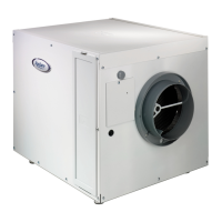
LEVELING AND RAISING THE DEHUMIDIFIER
The feet can be adjusted to level the unit and accommodate
drain ttings and condensate pans as required. Leveling is
required to ensure proper drainage from the dehumidier.
If installing a condensate pump (see FIGURE 11) to the side of
the unit more elevation than can be provided by the adjustable
feet may be needed. Risers (Part #5879) or hanging kits (Part
#5822) are available to lift the dehumidier higher off the oor.
INSTALLING A CONDENSATE PAN UNDER THE DEHUMIDIFIER
Always install the dehumidier in or above a condensate pan
when locating it above a nished space� Adhere to local codes
regarding draining of the condensate pan� If a condensate
pump is needed, make sure it is in the condensate pan as well�
Install a oat switch in the condensate pan and/or use the
overow wires/terminals on the condensate pump to stop the
dehumidier should overow occur. See WIRING TO A FLOAT
SWITCH on page 9�
90 -2304
A. ELECTRICAL SERVICE ACCESS THIS SIDE
B. FILTER
C. 8’ POWER CORD
0.38“ MIN
2.00“ MAX
CONNECTS TO
3/4" ID DRAIN TUBE
FIGURE 10: LEVELING THE UNIT
90 -2305
INSTALLING THE DEHUMIDIFIER
English 7