© Ikonix USA
18
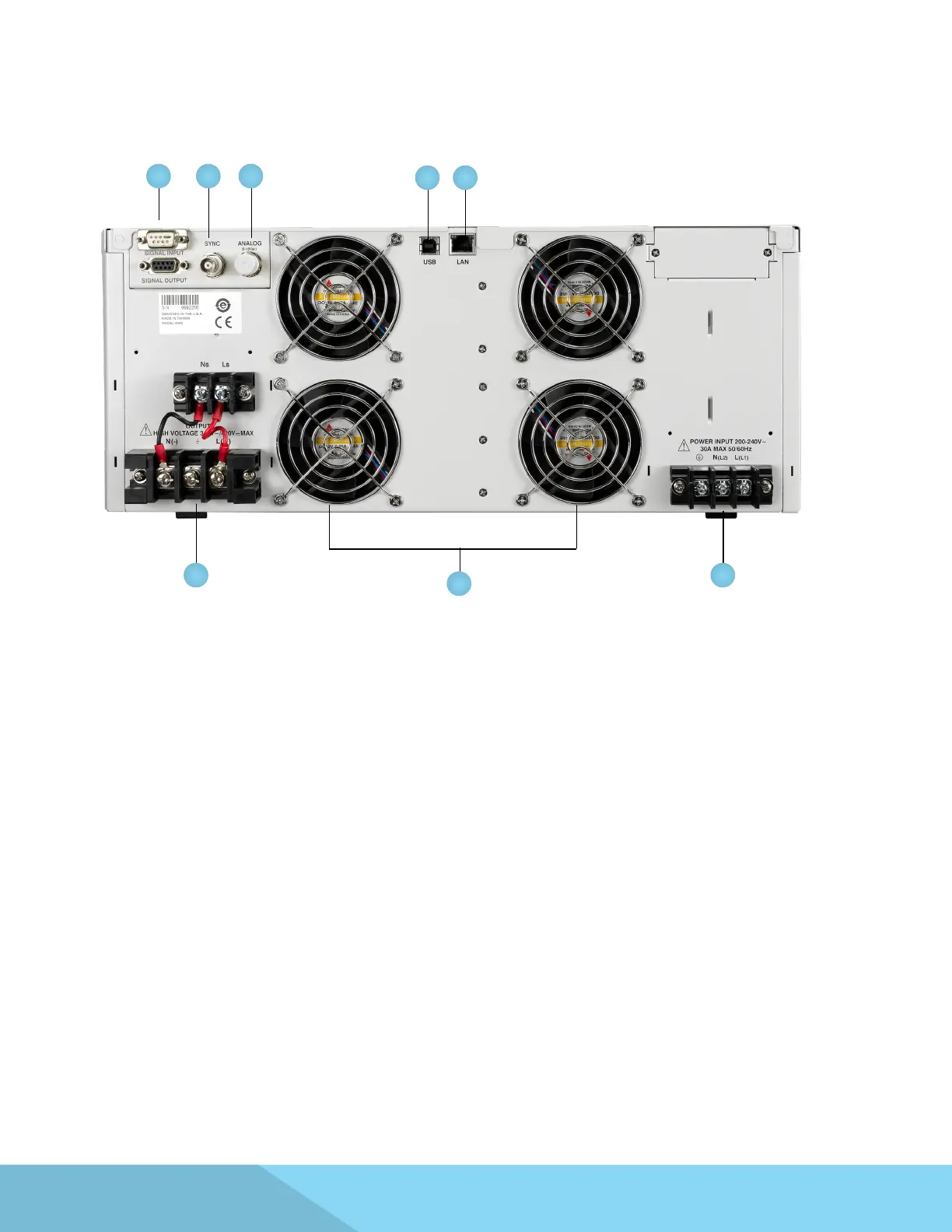
3.3.2 Rear Panel Controls
2 3
1
4
5 6
7
Model 8540
8
1. Thermal Fans - Used to cool the instrument. Automatically controlled.
2. Signal Input/Output Connectors
a. Signal Input: 9-Pin D-type subminiature male connector for remote control of OUTPUT ON,
OUTPUT OFF/RESET, Output Verify, File Recall, Trigger, and REMOTE INTERLOCK DISABLE functions.
b. Signal Output: 9-Pin D-type subminiature female connector for monitoring FAIL and
TEST-IN-PROCESS output relay signals.
3. Sync Output Connector - Provides the capability to monitor a 5 Vdc output signal.
4. Analog Input Signal Connector 10V – The 10V analog connector allows you to remotely set the
voltage applied to the device under test and measure the actual voltage and current.
5. USB Interface Port - Interface used to control, program, and capture data via a serial interface.
6. Ethernet LAN Interface Port - Interface used to control, program, and capture data via a LAN.
7. Input Power Terminal Block/Receptacle – Model 8505 has a standard input receptacle. Models 8512,
8520 and 8540 come with terminal block to connect input power lines to the instrument. Line,
Neutral and Earth Ground screw terminals provide a secure connection. Please reference the
instrument specications and section 2.5 Power Cable for details on input wire specications.
8. Output Terminal Block – Terminal block to connect output power lines for the device under test
or load. Line, Neutral, Ground, Sense(L) and Sense(N) screw terminals provide a secure connection.
Please reference the instrument specications and section 2.5 Power Cable for details on output wire
specications.