© Ikonix USA
53
6. Remote PLC
Two 9-pin “D” type connectors mounted on the rear panel provide input signals and output information for
remote control.
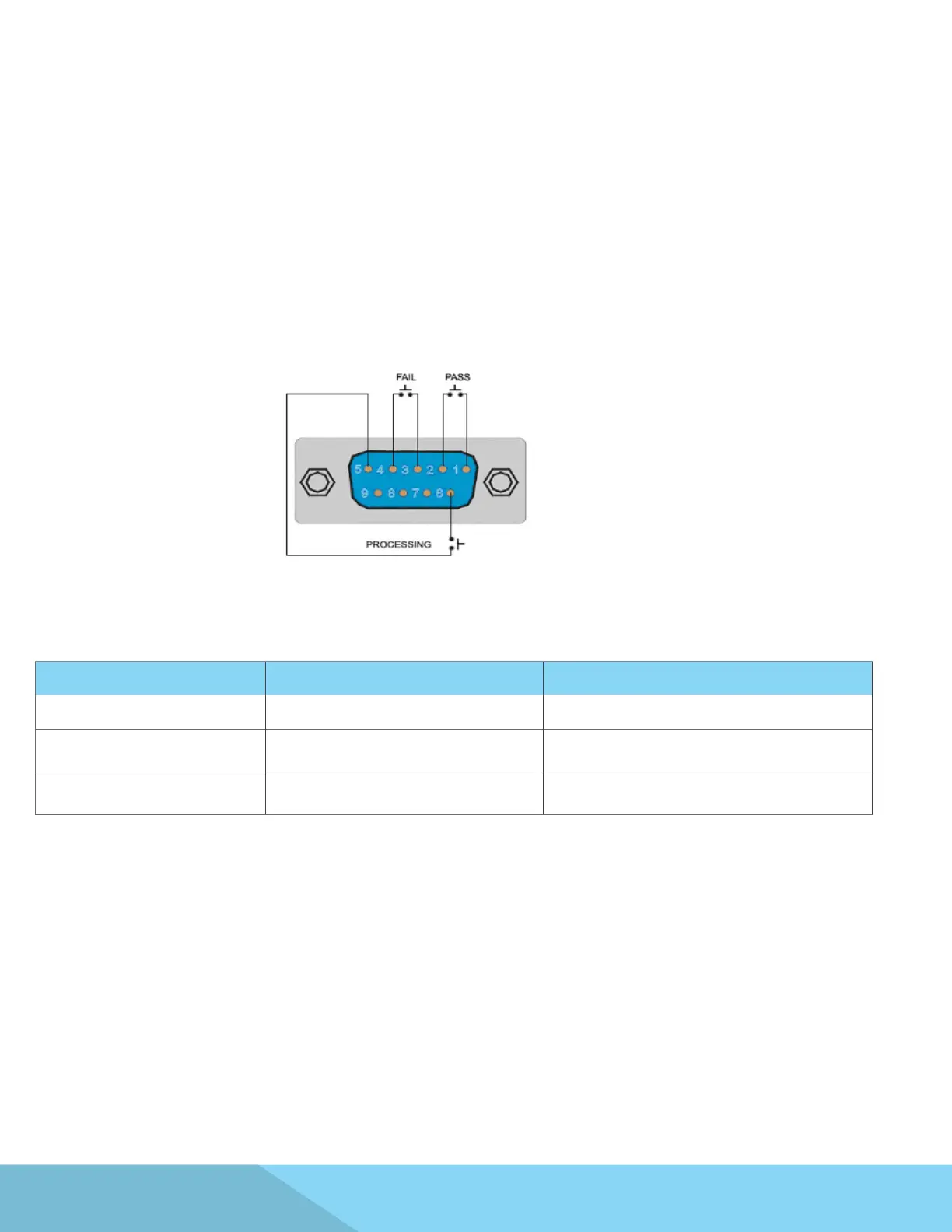
The rear panel Signal Output connector of the APT 8500 Series provides output signals to remotely monitor
PASS, FAIL, and PROCESSING conditions via a 9-Pin D-type connector. When a terminal becomes active the
relay closes thereby allowing the external voltage to operate an external device. These are normally open free
contacts and will not provide any voltage or current. The ratings of the contacts are 125 VAC / 1 Amp (30 VDC
/ 0.5 Amp).
Signal Output
The following table provides the conditions of each pin and the relay state:
Condition Pins Relay State
PASS Connection between PIN 1 & PIN 2 Closes on PASS and is opened on next test initialized
FAIL Connection between PIN 3 & PIN 4
Closes on FAIL and is opened when next test is
initialized
PROCESSING Connection between PIN 5 & PIN 6
Closes when test initialized and opens after test is
completed
The rear panel Signal Input connector of the APT8500 Series can be used to control any test operation via
remote. The 9-Pin D-Type connector enables remote operation for OUTPUT, RESET, Remote Interlock, File
Recall and Trigger functions. Remote functions will be activated once the PLC Remote parameter from the
System menu is turned on. When the PLC Remote paramater is turned on, you are not able to initiate a test
from the front panel OUTPUT/REST Key. However, when there is an abnormal output detected you can reset
by pressing either the OUTPUT/REST key or through the PLC remote.
Signal Input