© Ikonix USA
70
7.5 GPIB Interface
Connection is usually accomplished with a 24-conductor cable with a plug on one end
and a connector at the other end. Devices may be connected in a linear, star or combination
conguration.
The standard connector is the Amphenol or Cinch Series 57 Microribbon or AMP CHAMP type. The GPIB
uses negative logic with standard transistor-transistor logic (TTL) levels. When DAV is true, for example, it
is a TTL low level (≤ 0/8 V), and when DAV is false, it is a TTL high level (≥ 2.0 V).
Restrictions and Limitations on the GPIB
• A maximum separation of 4 m between any two devices and an average separation of 2 m over the
entire bus.
• A maximum total cable length of 20 m.
• No more than 15 device loads connected to each bus, with no less than two-thirds powered on. For
example 1 GPIB controller and a maximum of 14 GPIB instruments.
• Note: A bus extender, which is available from numerous manufacturers, is available to overcome these
limitations.
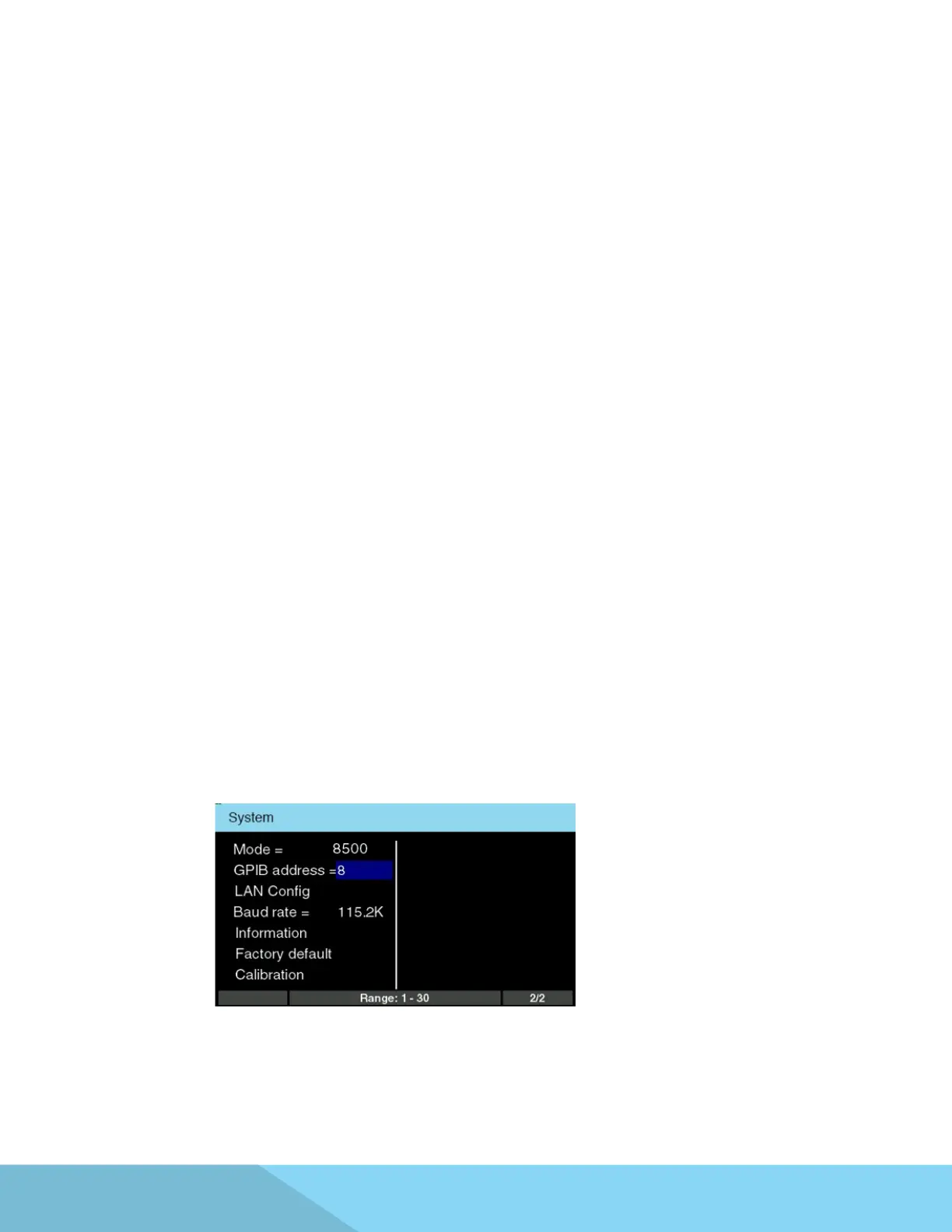
Each device on the GPIB (IEEE-488) interface must have a unique address. You can set the address of the
8500 series to any value between 0 and 30. The address can only be set from the front panel. The address
is stored in non-volatile memory and does not change when the power has been turned o or after a
remote reset.
Note – The GPIB address is set to 8 when the instrument is shipped from the factory:
7.5.1 GPIB Address