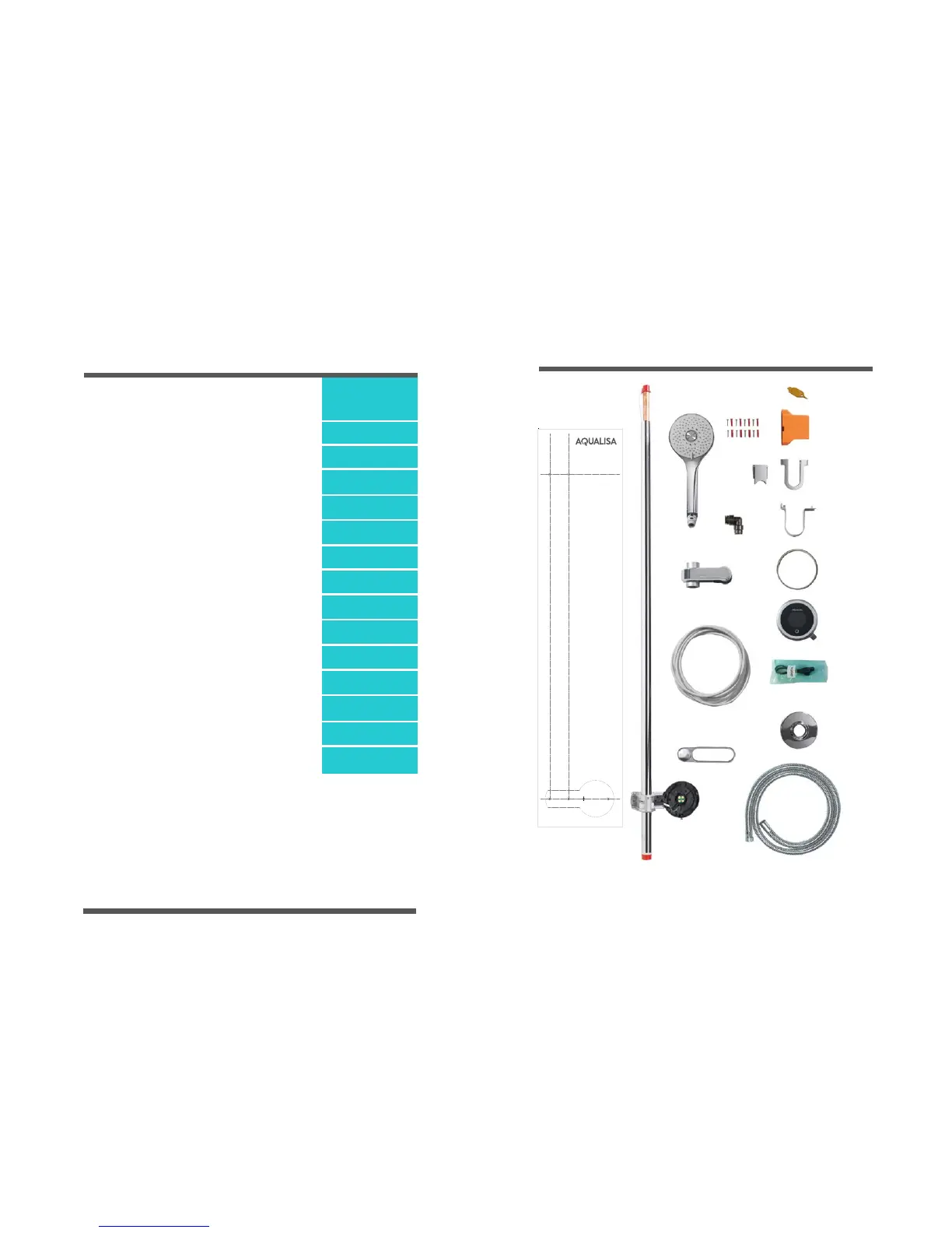
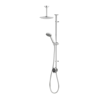
COMPONENTS
Data cable,
(already fitted to rail)
2 3
Quartz
TM
smart valve components not shown, refer to Quartz
TM
smart valve installation guide
for more details.
CANBUS
Converter
Vita
TM
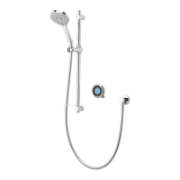
Shower head
PINCH GRIP
TM
Ceiling
cover plate
Riser rail
Controller
back plate
Gel holder
Shower hose
Top rail
bracket
Rail insert
cover plate
Place your level here
Hole diameter
for guidance
purposes only
Hole diameter
for guidance
purposes only
Minimum distance between top
bracket and the ceiling is 100mm
Ensure vertical
alignment by
using a spirit
level against the
vertical lines if
necessary
CEILING MOUNTED FIXING TEMPLATE
Part No: 703127 Issue 01 Jan 17
Fixing template
Q
TM
smart
controller
CANBUS
Data Cable
90° Push
fit Elbow
Stardust Silver
accent ring
INDEX
COMPONENTS PAGE 3
SAFETY INFORMATION PAGES 4 & 5
GRAVITY SYSTEMS PAGE 5
HIGH PRESSURE/COMBINATION BOILERS PAGE 5
CONNECTION TO SUPPLIES PAGE 6
FLUSHING PAGE 7
Q
TM
CONTROLLER INSTALLATION PAGE 8
ATTACHING ACCESSORIES PAGE 15
WALL MOUNTED FIXED HEAD PAGE 16
CEILING MOUNTED FIXED HEAD PAGE 19
BATH OVERFLOW AND FILLER PAGE 21
COMMISSIONING PAGE 24
WATER SAVE MODE PAGE 25
CLEANING AND MAINTENANCE PAGE 25
TROUBLE SHOOTING GUIDE PAGE 26
Data cable
removal tool