7.1CONNECTION DIMENSIONS AND COMPONENTS
15
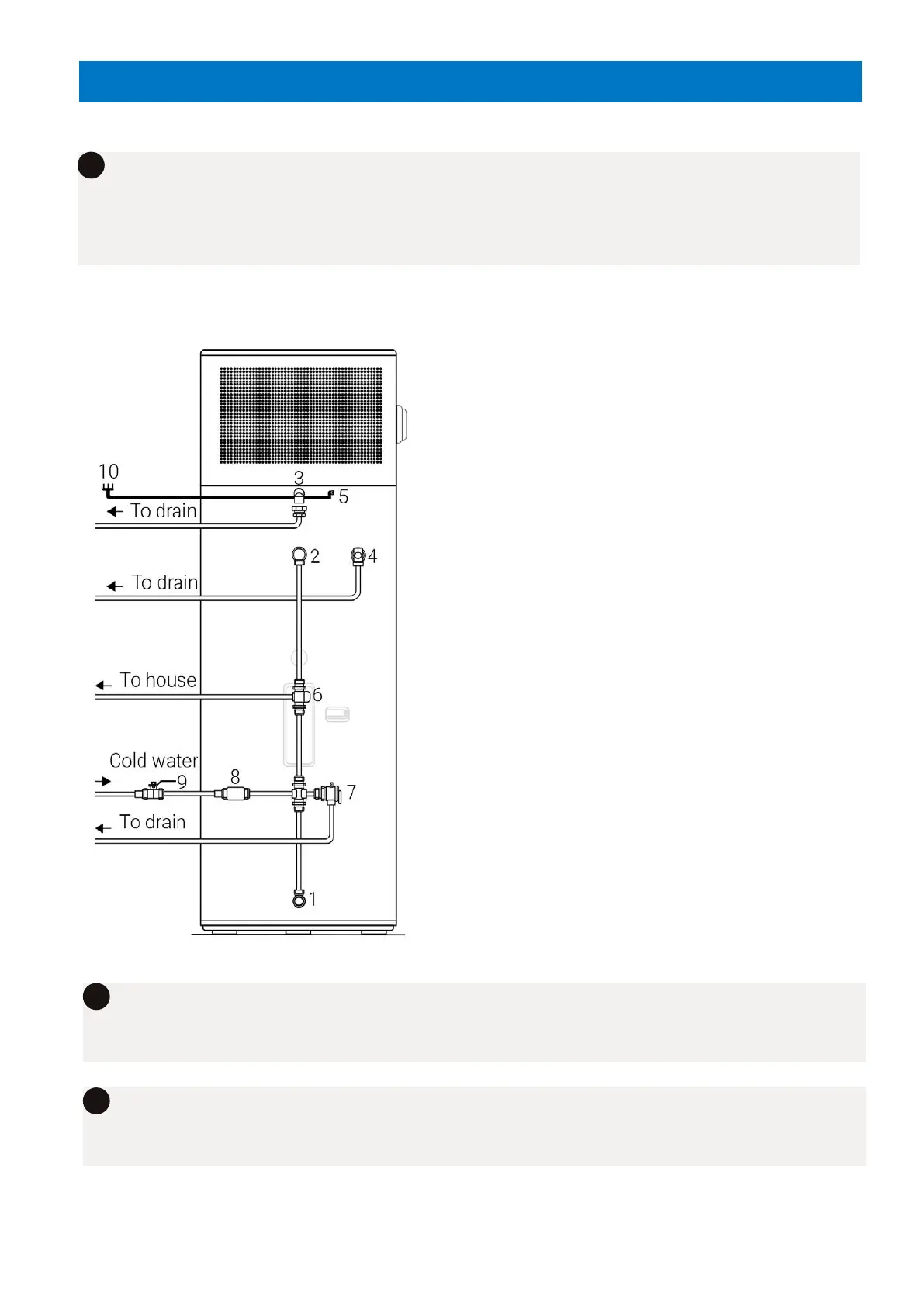
PLUMBING SCHEMATICS
The following instructions and schematics have taken into account standards AS4324,
AS4020, AS1056.1, AS/NZS2712, AS/NZ3350.240/30/30.2, AS3498 and represents
an optimum installation procedure for this unit however when installing please ensure
minimum requirements are met for all state & local councils.
i
1 Cold Water supply outlet
(G 3/4” female thread)
2 Hot Water Outlet
(G 3/4” female thread)
3 Condensing drainage Elbow & Hose
(supplied with system)
4 PTR Relief Valve
supplied with system)
5 Electrical Cable / Plug
6 Tempering Valve
(high performance recommended)
7 Expansion Control Valve (ECV)
(if required by council 700kPa)
8 Pressure Reduction Valve
(if required 500kPa)
9 Non-return/Isolation Valve
10 Isolation Switch / G.P.O
The electrical connection to this product must be via a
16A RCD/MCB or RCBO with a test button function.
The product must be connected to a mains water supply with a supply pressure of
no less then 150kPa and no more then 500kPa (if inlet pressure exceeds 500kPa a
pressure reduction valve is required.
i
This product is designed to be connected permanently to mains water using copper
piping. The use of flexible hose sets or other types of connections is not approved.
i