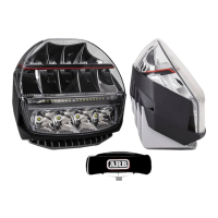
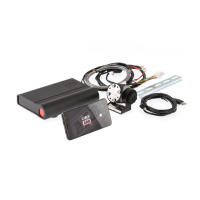
Harness Installation
Refer to Figure 1 for the harness drawing referenced in this instruction.
1. Remove the negative (-ve) cable from the vehicle batery (or bateries if applicable).
2. Lay out the harness in the engine bay and mount the four fuse holders in a convenient location. Please
note, if required, the three blade fuses can be stacked together.
3. Feed the LCM connector on the harness through a grommet on the firewall and pull through into the
vehicle cabin. To assist, it is recommended to fold back the cable and pull the connector through tail
first. If required, apply lubricant.
4. Securely mount the LCM behind the vehicle dashboard with cable ties or fasteners.
5. Connect the LCM connector with the harness connector.
6. Mount the switch in a convenient location on the vehicle dashboard. Ensure the dashboard surface is flat
and smooth. ARB recommends using M Primer 94 to prepare the dashboard surface for good adhesion.
Various mounting options are available for this switch:
a. The switch cable can be rotated rearwards for hidden cable installation. A hole in the dashboard is
required for the cable.
b. The switch cover can be removed and the ARB buton rotated for reverse installation. This will place
the QS and QS butons at the top rather than at the botom of the switch.
c. Removing the switch cover gives access to screw holes inside the switch for screwing onto the
mounting surface.
7. Connect the switch connector with the LCM connector.
8. Connect high beam trigger connector with the vehicle high beam wire. This connector suits ARB
plug-and-play headlight connectors (purchased separately). If the vehicle has alternative headlight
connectors, cut the connector and join the yellow wire with the vehicle high beam wire.
9. For all negatively switched headlamp vehicles, complete this step. Otherwise, continue to Step 10. On
the harness, cut and remove the connector from the high beam trigger connector (yellow) wire. Obtain a
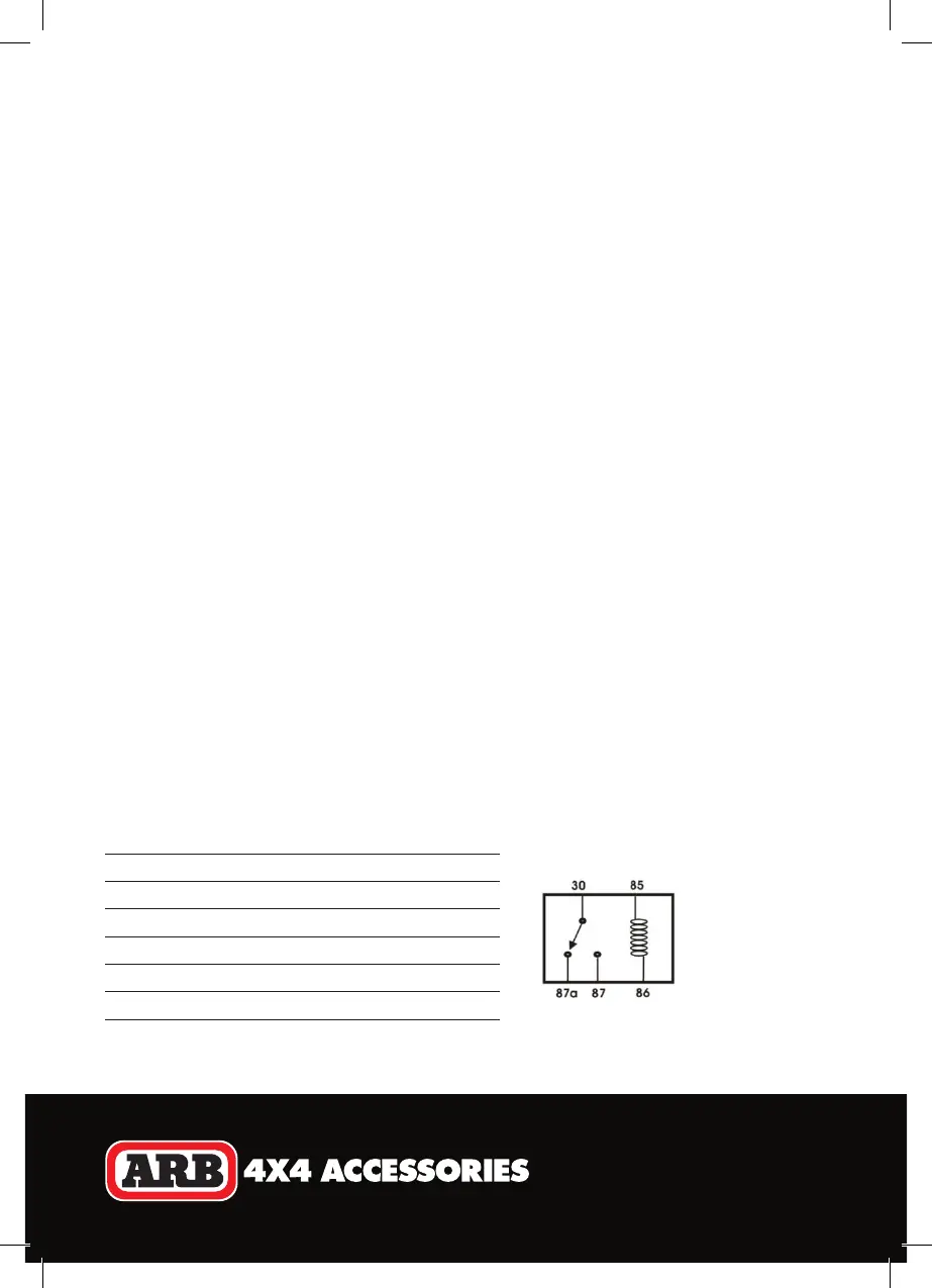
switching relay and connect the relay terminals as per below:
Relay Terminal Connection
85 Vehicle positive high beam wire
86 Vehicle negative high beam wire
87 High beam trigger wire (yellow)
87a -
30 Vehicle ignition circuit
 Loading...