3-12
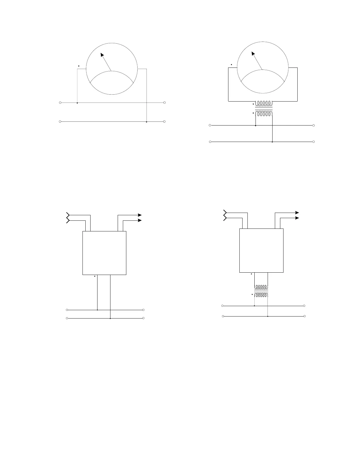
a) Voltmeter, Typical Installation,
no Potential Transformer
V
L
1
N
L
1
N
L
I
N
E
V
Inst.
Pwr.
+
-
Output
L
1
N
L
I
N
E
L
1
N
L
O
A
D
c) Voltage Transducer, Typical
Installation, no Potential Transformer
L
O
A
D
Figure 1
Single-Phase Voltage Meters and Transducers,
Typical Circuit Connections
V
L
I
N
E
L
1
N
L
1
N
b) Voltmeter, Typical Installation,
with Potential Transformer
L
O
A
D
V
Inst.
Pwr.
+
-
Output
L
1
N
L
I
N
E
L
1
N
d) Voltage Transducer, Typical
Installation, with Potential Transformer
L
O
A
D