3-13
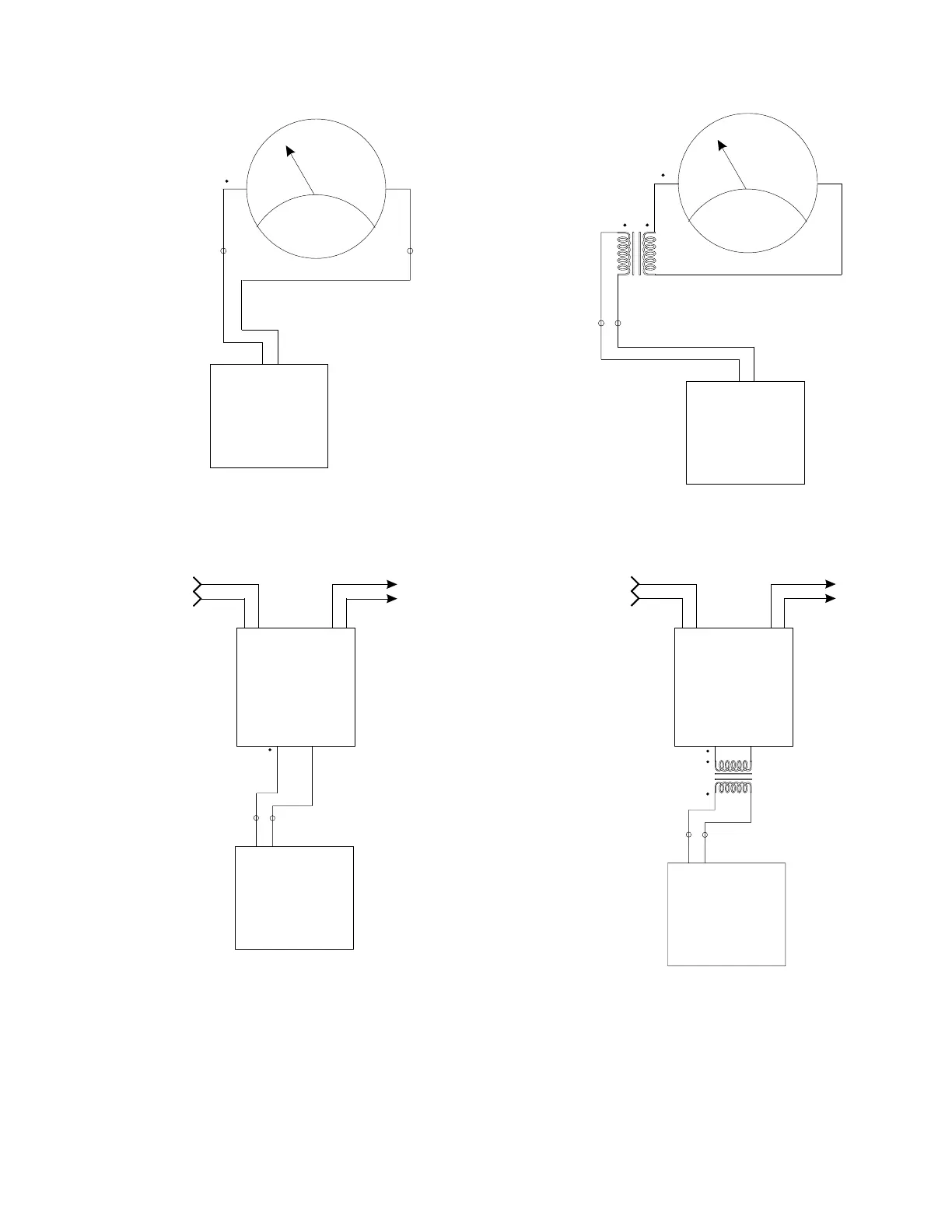
a) Voltmeter Calibration Connections,
no Potential Transformer
V
V
Inst.
Pwr.
+
-
Output
c) Voltage Transducer Calibration Connections,
no Potential Transformer
Figure 2
Single-Phase Voltage Meters and Transducers,
Typical Circuit Connections
1040C
V
out
1040C
V
out
RB
V
Inst.
Pwr.
+
-
Output
d) Voltage Transducer Calibration Connections,
with Potential Transformer
1040C
V
out
RB
V
b) Voltmeter Calibration Connections,
with Potential Transformer
1040C
V
out
R
B
RB