7
2
+
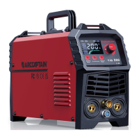
Welding process
selection area
Parameter switch button
MIG LED
MMA LED
Lift TIG LED
3
+
Current
adjustment
Current adjustment knob
Parameter LED display
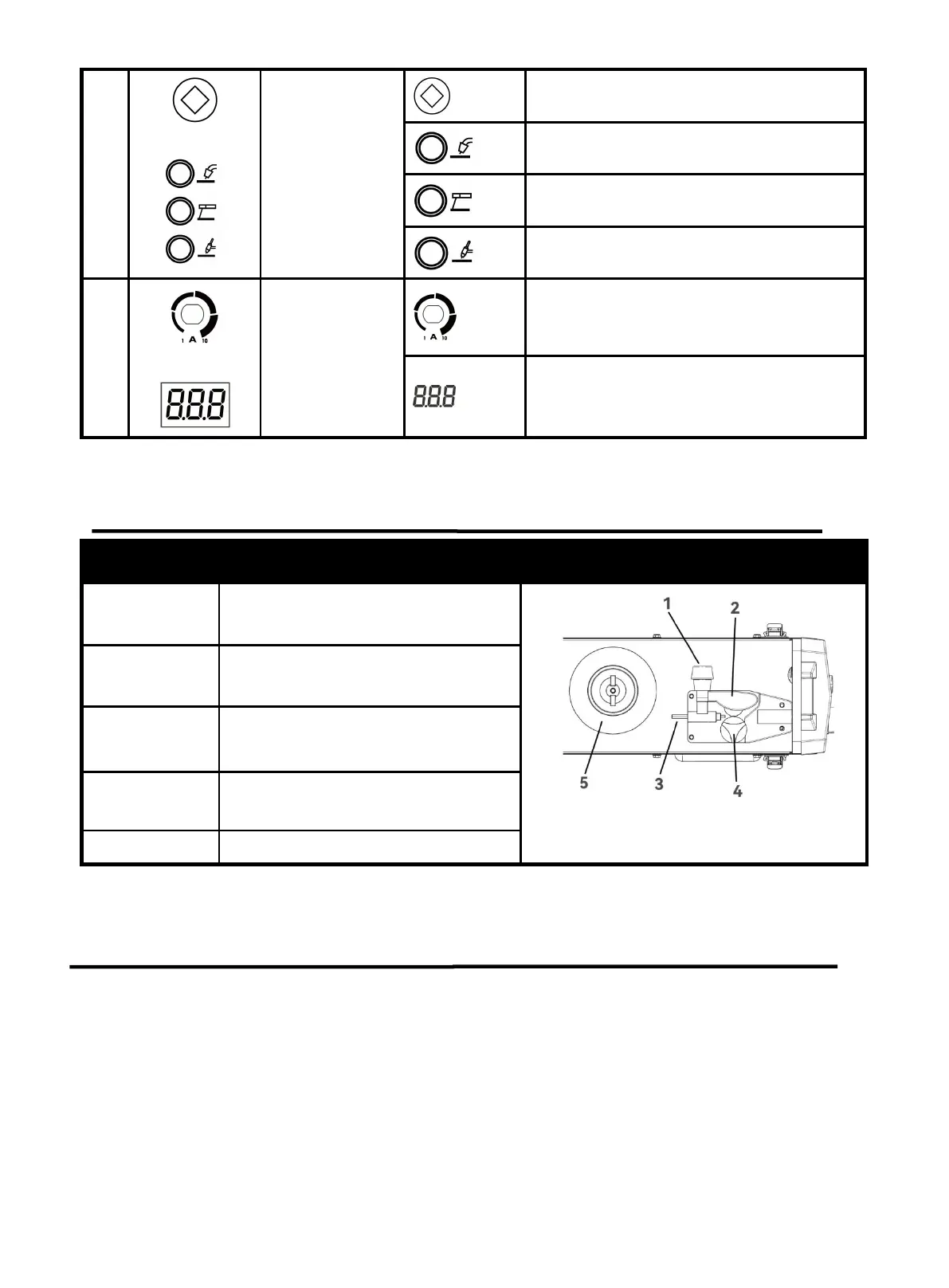
3.3 Wire Feeding Description
Part name Function Picture
1. Feed
Tensioner
Fixed the Idler Arm and adjusts the
pressure on the wire
Figure 5 Inside wire feeder
2.Idler Arm
Press down on the welding wire
3. Wire Inlet
Liner
Guide the welding wire into the wire
feeder
4. Feed Roller
V0.8-0.9 feed roller,Transfer welding
wire
5. Wire Spool
Fixed welding wire spool
3.4 Nameplate
On the machine, there is a plate that includes all the operating specifications for your new unit. The serial
number of the product is also found on this plate.
The duty cycle rating of a welder defines how long the operator can weld and how long the welder must
rest and be cooled. Duty cycle is expressed as a percentage of 10 minutes and represents the maximum
welding time allowed. The balance of the 10-minute cycle is required for cooling.
For example, a welder has a duty cycle rating of 60% at the rated output of 160A. This means with that
machine: you can weld at 160 A output for six (6) minutes out of 10 with the remaining four (4) minutes
required for cooling. The duty cycle of your new welder can be found on the data plate affixed to the
https://www.arccaptain.com/