14
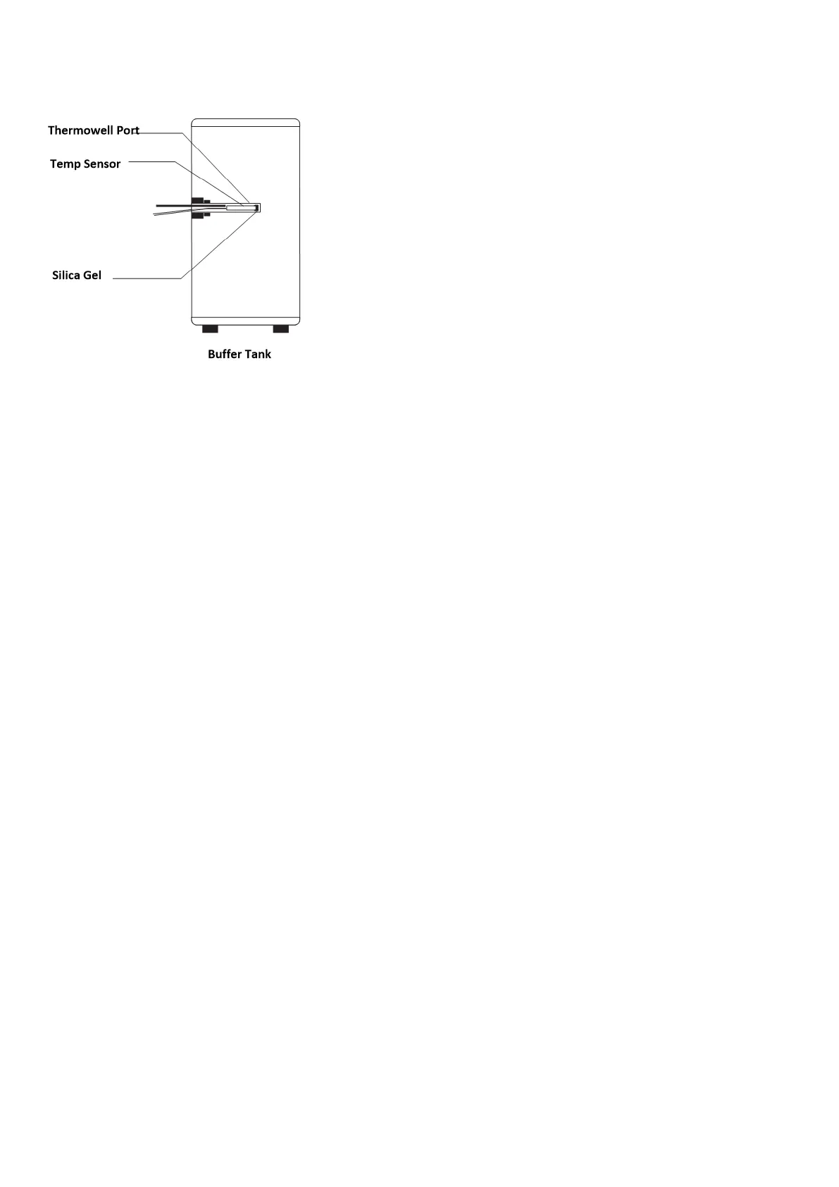
Installation of the Temperature Sensor
1. Firstly, place a small amount of heat conductive silicone onto the front of the temperature sensor, then
insert it into the temperature thermowell port.
2. Next, push the temperature sensor through to the end of the thermowell, then mark the depth of the pin
on the sensor wire.
3. Next, pull the senor and check that the position of mark is at the same depth as the end of the sensor well
to ensure the sensor is inserted into the sensor well all the way (use a thin wire to check depth of sensor
well)
4. Finally, seal the inlet of the temperature detector with silicone.
Electrical Wiring
• The heat pump should use dedicated power cable with voltage and current capacity following the electrical code
given the voltage and amperage rating of the heat pump and circulating pump
• Outdoor rated disconnect must be installed near the heat pump as per local codes.
• The power cable for the heat pump must be outdoor rated and protected in a metal jacket or conduit.
• The heat pump power supply circuit must have a grounding wire, which should connect with a reliable and
effective external ground wire.
• Wiring must be installed by qualified electrician with reference to the circuit diagram.
• The layout of power wires/cables and control cables should be neat, well supported and with power and control
cables separated so they cannot interfere with each other.
• When power lines and control cables are parallel, the wires must be placed inside conduit, with appropriate
distance between the cables.
• For electrical connection of the heat pump, pull the following wiring through the wiring hole of the electrical
box, then connect to the appropriate terminals in the electrical box according to wiring diagram:
· Power cable (240 VAC)
· Digital Controller cable
· Electric back up heater switch control cable
· Temperature tank sensor cable
· Pump cable (240 VAC)
· Optional 3-way Valve cable (240 VAC)