49
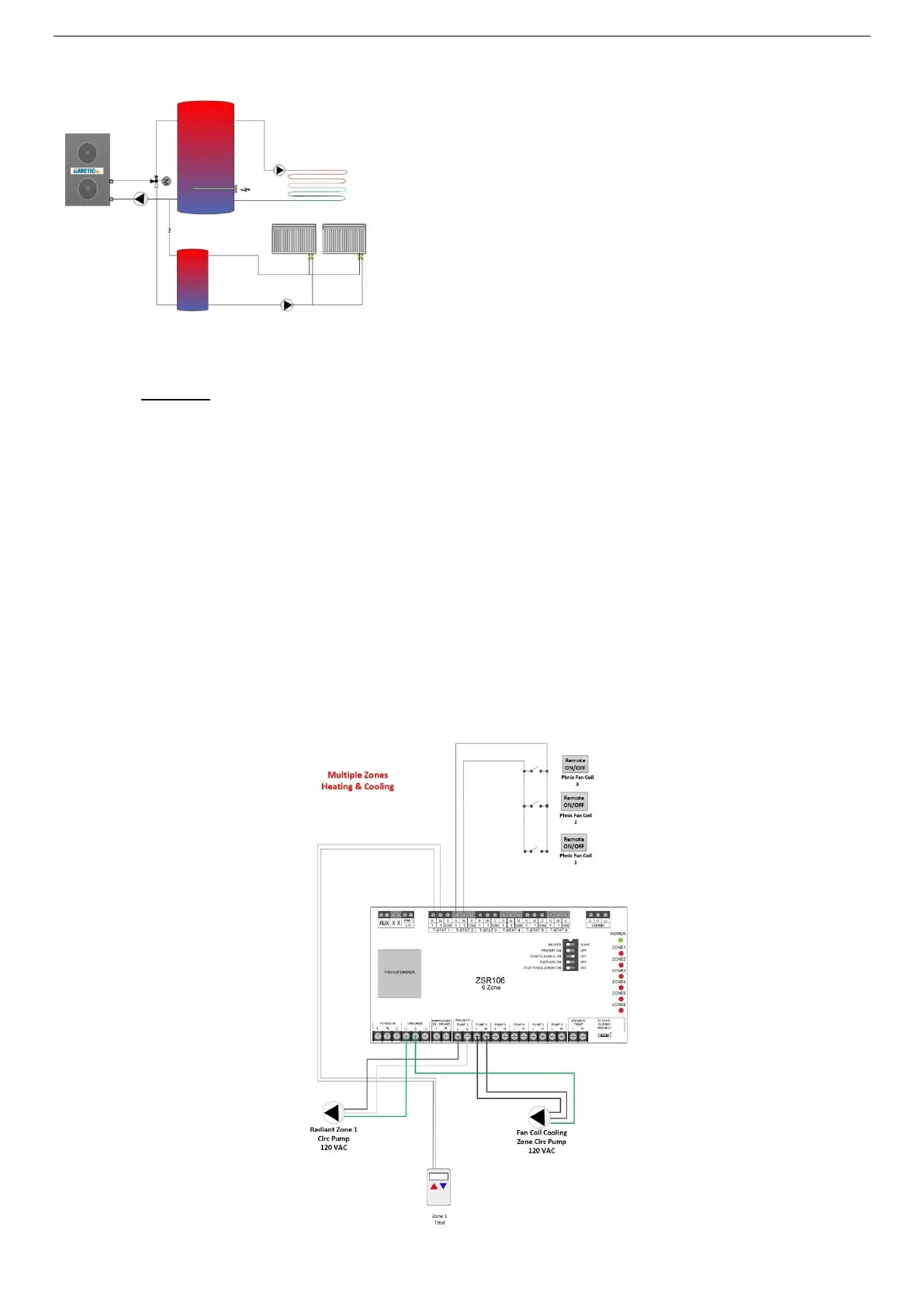
H-F - Wiring – HYDRONIC HEATING (H) & COOLING Fan Coil (F)*
The fan coils are equipped with their own thermostat mounted on the unit as well as an internal 3-way
valve, and pump output activation switch REMOTE ON/OFF. The setting of the fan coil should be set to
COOLING not Auto. When a cooling call is received by the units, the fan coil will open the internal 3-way
valve and close its dry contact switch (remote on/off). This closed Remote ON/OFF connection switch is
connected to a T-Stat (R & W) input on a Caleffi Zone Relay. This in turn cause the fan coil circulation
pump to turn on and circulate cold water from the cold buffer tank to the fan coil. When more than one
fan coil is used the Remote ON/OFF connections will be wired in parallel such that when any single fan
coil requires cooling it will activate the cooling circulation pump. The variable speed pump should be set
to constant pressure such that it will increase and decrease its speed depending on the number of zones
that are actively opened.
In Radiant Heating a separate heating thermostat will be used. A standard thermostat will have a R and a
W heating terminal outputs. Some thermostats also require 24 VAC supply to operate and if so, you will
also connect the C on these 3 wire T-Stats. Simply connect the R & W terminals to the second T-Stat 2 on
the Callefi Zone Relay. When a heating call occurs the circulation pump will then be activated. The switch
on the Pump Relay will close and provide 120 VAC to the pump (consult Caleffi Zone Relay manual for
proper pump wiring as this differs between models)