52
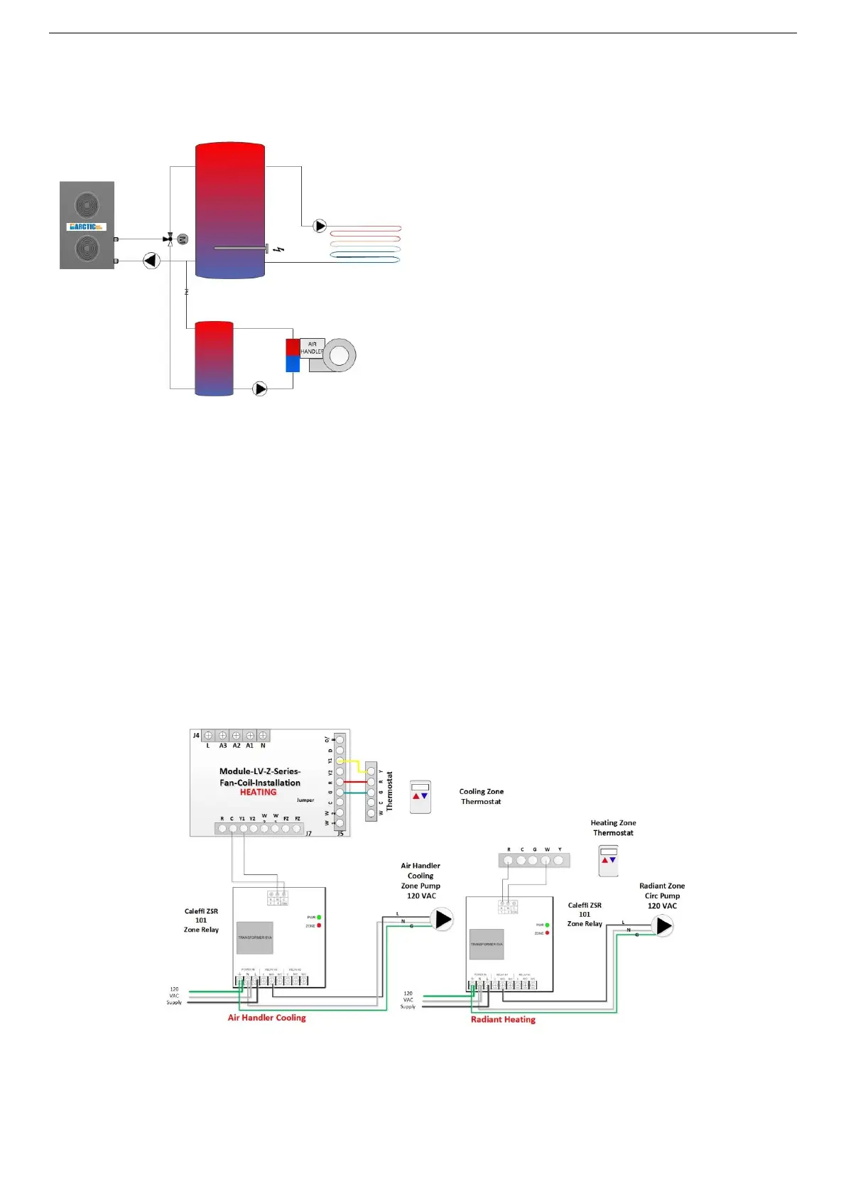
H-A Wiring – HYDRONIC HEATING (H) & COOLING Air Handler (A)*
A common thermostat will have a R (24 VC) and a Y cooling terminal outputs. Some thermostats also
require 24 VAC supply to operate and if so, you will also connect the C on these 3 wire T-Stats. Connect
the R and Y terminals to the R and Y1 terminal on the J5 terminal strip on the fan coil. (consult Air Handler
Wire Manual for proper pump wiring as this can differ between models). This in turn will signal the fan
coil to optimize its speed for cooling. Connect the Y1 and C on the output terminal J7, to the C and W
thermostat terminals on the ZSR 101 board. On a Cooling call Y1 on the output of the air handler is
energized, this in turn will cause the relay contact to close turning on the cooling circulation pump.
NOTE a cooling buffer tank is required. With this layout we assume the controller unit has been set to
“Cooling” or “Hot Water & Cooling” and the cooling buffer tank is always chilled.
For the radiant floor pump, we use a Caleffi Zone Relay to activate the circulation pump on a heating call.
The W and R terminals on the same T-Stat used for cooling are connected to the R & W terminals on the
Zone Relay T-Stat. When a heating call is active the R and W close causing the pump relay to turn on
(consult the air handler and Caleffi manuals as wiring differs between models).