50
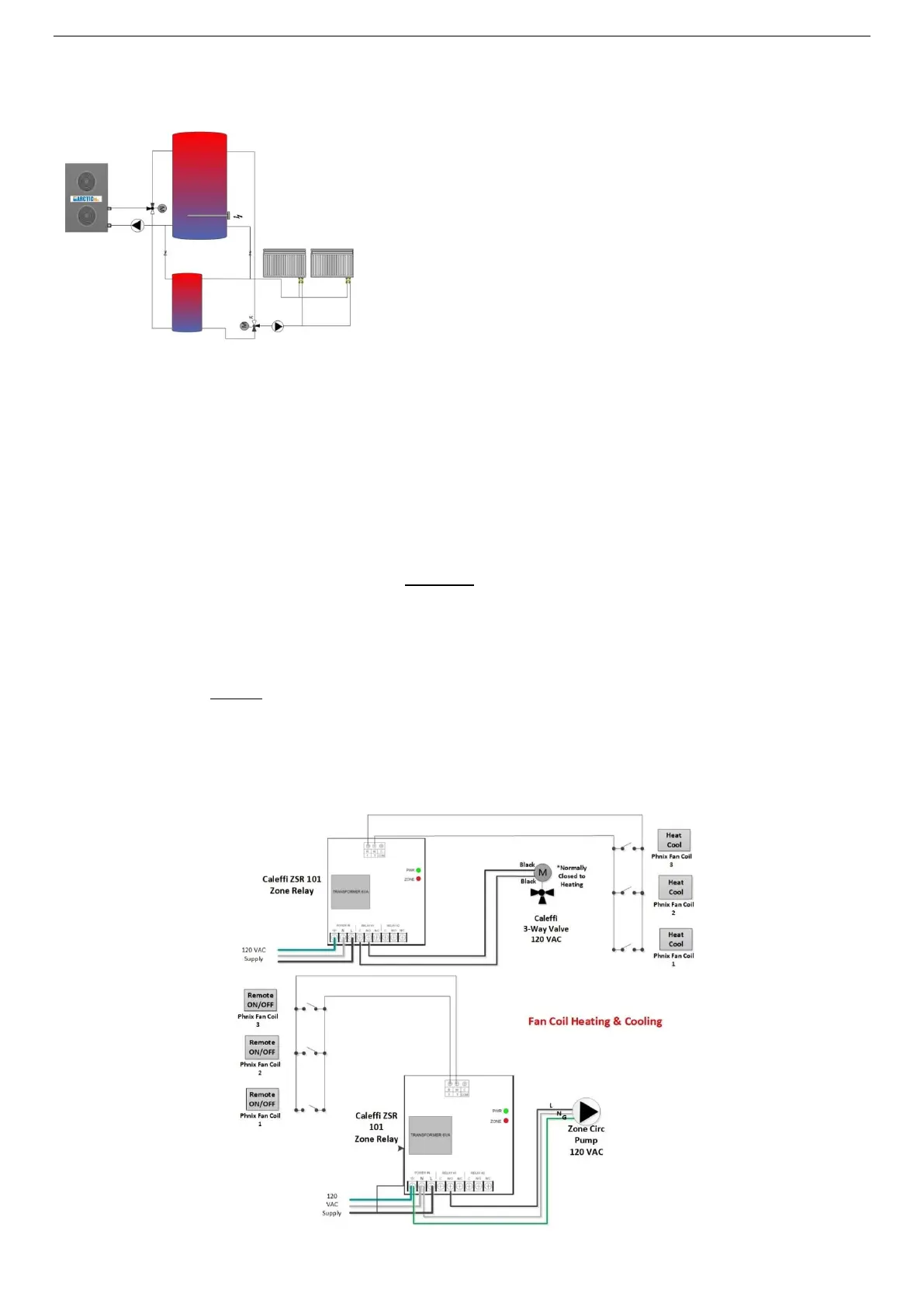
F-F - Wiring – Fan Coil HEATING (F) & Fan Coil COOLING (F)*
The Fan coils are equipped with their own thermostat mounted on the unit as well as an internal 3-way
valve and pump output activation switch. In this configuration the fan coil can be set to HEATING or
COOLING or AUTO. When a heating/cooling call is generated by the units, the fan coil will open the
internal 3-way valve and close its pump output switch “Remote ON/OFF”. This closed Remote on/off
switch will then active the variable speed pump using a Caleffi Zone Relay just like the thermostat did in
previous heating arrangement. When more than one fan coil is used the “Remote On/Off” switches will
be wired in parallel such that when any single fan coil requires heat it will activate the pump. The variable
speed pump should be set to constant pressure such that it will increase and decrease its speed
depending on the number of zones that are actively opened. On the Fan coil there is also a second
Heating/Cooling switch that is closed during HEATING. Like the “Remote on/off” this will be connected in
parallel if there are multiple fan coils and connected to a second T-Stat Terminal on a Caleffi Zone Relay
(can use two ZSR 101 or one ZSR 102/103). When this switch is closed it will cause the 3-way valve to
switch to the Normally Closed position causing the water flow to come from the heated buffer tank
instead of the chilled buffer tank. (consult Caleffi Zone Manual for proper pump wiring as this differs
between models). Note*: Pay close attention to the 3-way Valve NC/NO direction. Alternatively, the
relay can be wired so that on heating it is NO and Cooling NC. By changing the terminal on the Caleffi
Zone Relay to NC terminal there will be no power to the NC terminal in heating mode and power in
cooling.