P341/EN O/B11 Operation Guide
CHAPTER 1 Introduction
Page 6/22 MiCOM P341
Note: *May vary according to relay type/model
TRIP
ALARM
OUT OF SERVICE
HEALTHY
= CLEAR
= READ
= ENTER
SER N
o
DIAG N
o
I
n
V
x
V
n
V
V
1/5 A 50/60 Hz
SK1 SK2
User programable
function LEDs
Serial N
o
and
I
*
, V Ratings
Top cover
Fixed
function
LEDs
Bottom
cover
Battery compartment Front comms port Download/monitor port
Keypad
LCD
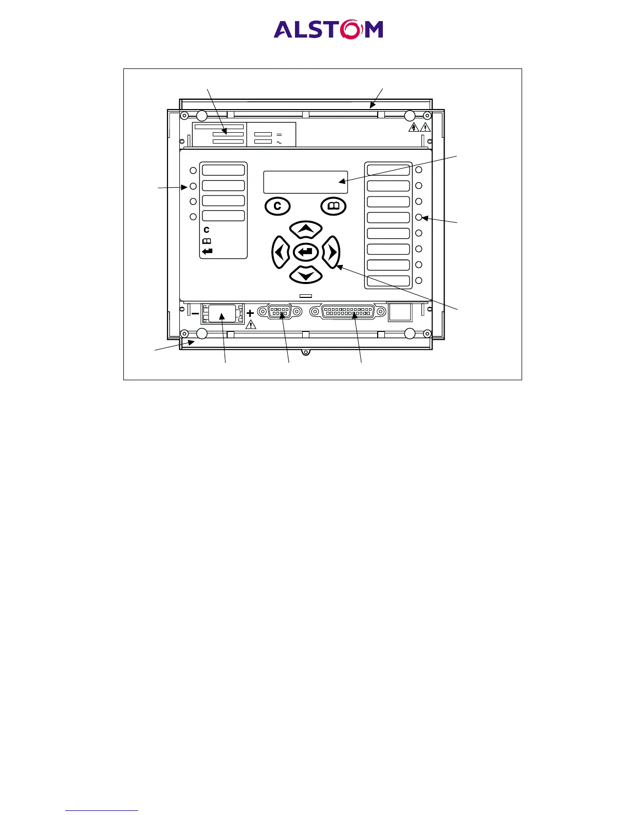
Figure 1: Relay front view
The front panel of the relay includes the following, as indicated in Figure 1:
− a 16-character by 2-line alphanumeric liquid crystal display (LCD).
− a 7-key keypad comprising 4 arrow keys (/, 6, 8 and 2), an enter key (5),
a clear key (0), and a read key (1).
− 12 LEDs; 4 fixed function LEDs on the left hand side of the front panel and 8
programmable function LEDs on the right hand side.
− Under the top hinged cover:
− the relay serial number, and the relay’s current and voltage rating information*.
− Under the bottom hinged cover:
− battery compartment to hold the 1/2 AA size battery which is used for memory
back-up for the real time clock, event, fault and disturbance records.
− a 9-pin female D-type front port for communication with a PC locally to the
relay (up to 15m distance) via an RS232 serial data connection.
− a 25-pin female D-type port providing internal signal monitoring and high
speed local downloading of software and language text via a parallel data
connection.