Operation Guide P341/EN O/B11
Commissioning and CHAPTER 3
Maintenance Page 9/80
MiCOM P341
Note: The use of a magnetic bladed screwdriver is recommended to minimise the
risk of the screws being left in the terminal block or lost.
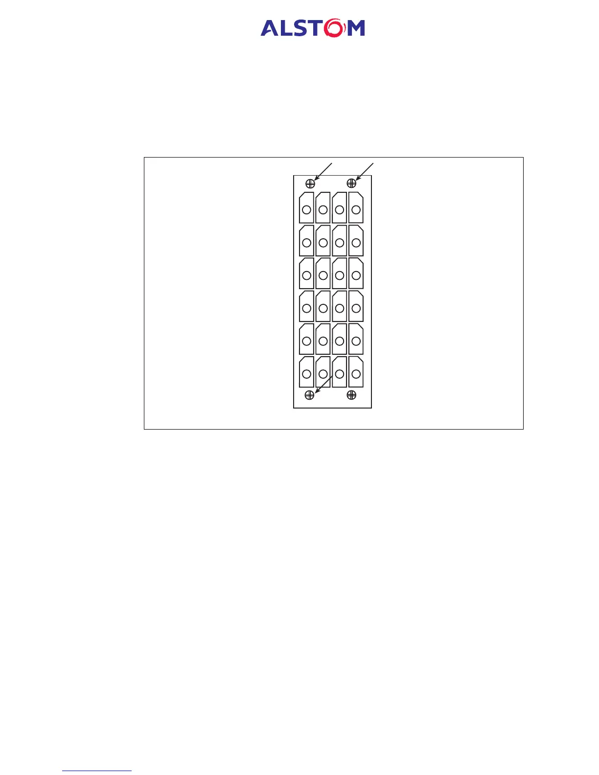
Pull the terminal block away from the rear of the case and check with a continuity
tester that all the shorting switches being used are closed. Table 1 shows the
terminals between which shorting contacts are fitted.
19
1
2
3
4
5
6
7
8
9
10
11
12
13
14
15
16
17
18
20
22
21
23
24
Heavy duty terminal block
Figure 2: Location of securing screws for heavy duty terminal blocks
4.1.3 Insulation
Insulation resistance tests are only necessary during commissioning if it is required for
them to be done and they haven’t been performed during installation.
Isolate all wiring from the earth and test the insulation with an electronic or brushless
insulation tester at a dc voltage not exceeding 500V. Terminals of the same circuits
should be temporarily connected together.
The main groups of relay terminals are:
a) Voltage transformer circuits
b) Current transformer circuits
c) Auxiliary voltage supply
d) Field voltage output and opto-isolated control inputs
e) Relay contacts
f) RS485 communication port
g) RTD inputs
h) Case earth
 Loading...


