P341/EN O/B11 Operation Guide
CHAPTER 1 Introduction
Page 8/22 MiCOM P341
Note: *May vary according to relay type/model
3.2 Introduction to the user interfaces and settings options
The relay has three user interfaces:
− the front panel user interface via the LCD and keypad.
− the front port which supports Courier communication.
− the rear port which supports one protocol of either Courier, Modbus,
IEC 60870-5-103 or DNP3.0. The protocol for the rear port must be specified
when the relay is ordered.
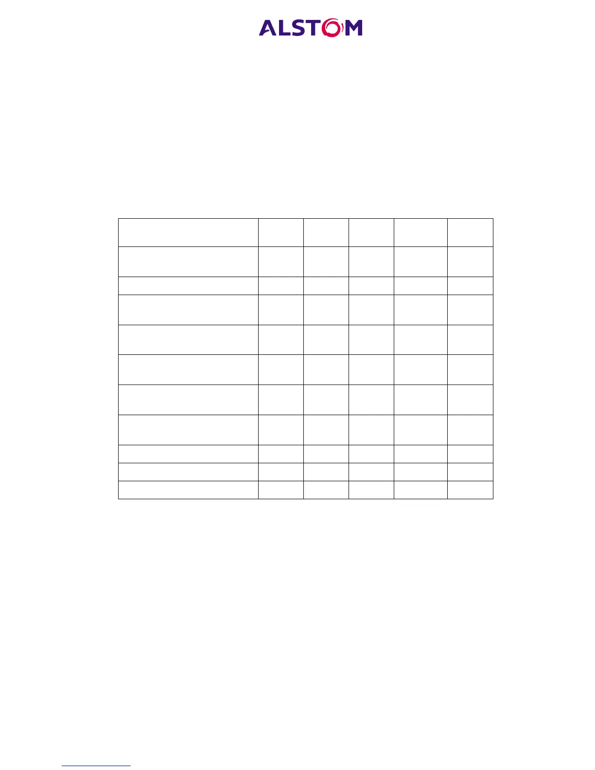
The measurement information and relay settings which can be accessed from the
three interfaces are summarised in Table 1.
Keypad
/LCD
Courier Modbus IEC60870 DNP3.0
Display & modification of all
settings
•••
Digital I/O signal status • • • • •
Display/extraction of
measurements
•••••
Display/extraction of fault
records
•••
Extraction of disturbance
records
••
Programmable scheme logic
settings
•
Reset of fault & alarm
records
•••••
Clear event & fault records • • • •
Time synchronisation • • •
Control commands • • • • •
Table 1:
3.3 Menu structure
The relay’s menu is arranged in a tabular structure. Each setting in the menu is
referred to as a cell, and each cell in the menu may be accessed by reference to a
row and column address. The settings are arranged so that each column contains
related settings, for example all of the disturbance recorder settings are contained
within the same column. As shown in Figure 3, the top row of each column contains
the heading which describes the settings contained within that column. Movement
between the columns of the menu can only be made at the column heading level. A
complete list of all of the menu settings is given in Appendix A of the manual.
 Loading...


