Operation Guide P341/EN O/B11
Installation CHAPTER 2
MiCOM P341 Page 5/10
the correct test block to be easily identified during commissioning and maintenance
tests.
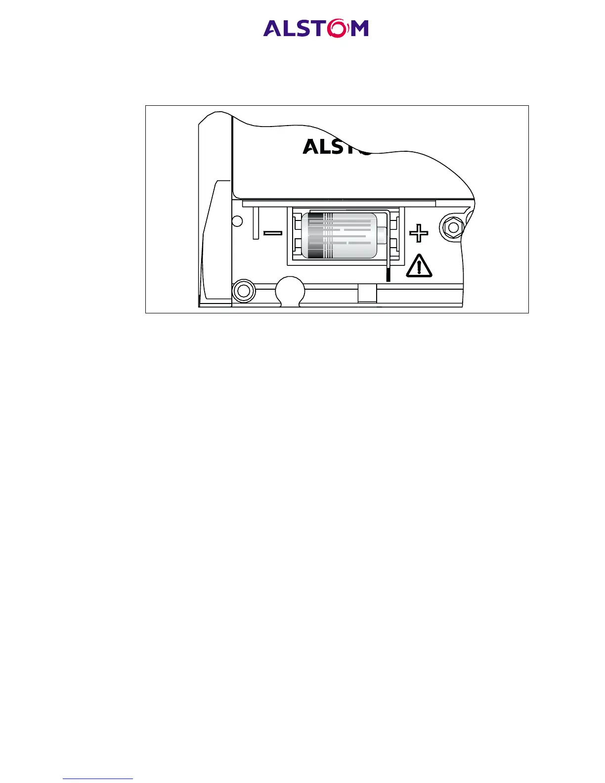
Figure 1: Location of battery isolation strip
If it is necessary to test correct relay operation during the installation, the battery
isolation strip can be removed but should be replaced if commissioning of the
scheme is not imminent. This will prevent unnecessary battery drain during
transportation to site and installation. The red tab of the isolation strip can be seen
protruding from the positive side of the battery compartment when the lower access
cover is open. To remove the isolation strip, pull the red tab whilst lightly pressing the
battery to prevent it falling out of the compartment. When replacing the battery
isolation strip, ensure that the strip is refitted as shown in Figure 1, i.e. with the strip
behind the battery with the red tab protruding.
5.1 Rack mounting
MiCOM relays may be rack mounted using single tier rack frames (our part number
FX0021 001), as illustrated in Figure 2. These frames have been designed to have
dimensions in accordance with IEC60297 and are supplied pre-assembled ready to
use. On a standard 483mm rack system this enables combinations of widths of case
up to a total equivalent of size 80TE to be mounted side by side.
The two horizontal rails of the rack frame have holes drilled at approximately 26mm
intervals and the relays are attached via their mounting flanges using M4 Taptite self-
tapping screws with captive 3mm thick washers (also known as a SEMS unit). These
fastenings are available in packs of 5 (our part number ZA0005 104).
Note: Conventional self-tapping screws, including those supplied for
mounting MIDOS relays, have marginally larger heads which
can damage the front cover moulding if used.
Once the tier is complete, the frames are fastened into the racks using mounting
angles at each end of the tier.
 Loading...


